
Page 42 - MetalForming January 2017
P. 42
Tooling by Design
By Peter Ulintz
Technology Forum for Die Shops
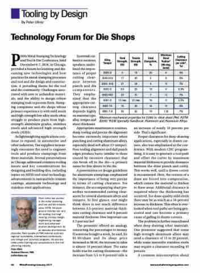
Alloy, Temper
Yield Strength, KSI
Tensile Strength, KSI
Total Elongation, %
Minimum Bend Radius* (90-deg. bend)
Cutting Clearance per side*, %t
3003-O
5
14
25
0
5%
3003-H14
17
20
5
0
6%
3003- H16
21
24
4
1t
7%
5052-O
9.5
25
19
0
6.5%
5052-H32
23
31
7
1t
7%
6061-O
12 max
22 max
16
0
5.5%
6061-T4
16
30
16
1t
6%
6061-T-6
35
42
10
1.5t
7%
PMA’s Metal Stamping Technology and Tool & Die Conference, held December 6-7, 2016, in Chicago, provided a forum for learning and dis- cussing new technologies and best practices for metal-stamping processes and tool and die design and construc- tion. A prevailing theme for the tool and die community: Challenges asso- ciated with new or unfamiliar materi- als, and the ability to design robust stamping tools to process them. Stamp- ing companies and die shops whose primary experience is with mild steels and high-strength low-alloy steels often struggle to produce parts from high- strength aluminum grades, stainless steels and advanced high-strength steels (AHSS).
As lightweighting applications con- tinue to expand, in automotive and other industries, Tier suppliers increas- ingly encounter the need to engineer tools and produce stampings from these materials. Several presentations in Chicago addressed common tooling issues and key considerations for designing and building dies, including topics on AHSS tool-steel technology, advancements in nanoparticle ceramic coatings, aluminum technology and stainless-steel applications.
Peter Ulintz has worked in the metal stamping and tool and die industry since 1978. His back- ground includes tool and die making, tool engi- neering, process design, engineering manage- ment and advanced product development. As an educator and technical
presenter, Peter speaks at PMA national seminars, regional roundtables, international conferences, and college and university programs. He also pro- vides onsite training and consultations to the met- alforming industry.
Peter Ulintz
Technical Director, PMA pulintz@pma.org
In several con- ference sessions, speakers under- lined the impor- tance of proper cutting clear- ance between punch and die components. They empha- sized that the appropriate cut- ting clearance depends highly on material type, alloy, temper and sheet thickness.
Minimum mechanical properties for 0.060-in.-thick sheet (Ref. ASTM B209) *ASM Specialty Handbook: Aluminum and Aluminum Alloys
Appropriate maintenance routines, sharp tooling and precise die alignment become extremely important when punching and cutting aluminum alloys, especially dead soft alloys (O-temper). Poor tooling alignment and dull punch edges produce burrs (similar to those caused by excessive clearance) that can break off in the die—a primary cause for fine slivers in the die.
A presentation on design guidelines for aluminum stampings emphasized the importance of being very precise in terms of cutting clearance. For instance, the accompanying chart pre- scribes recommended cutting clear- ances for several aluminum alloys and tempers. At first glance, one might think there is not much difference between 5.5-percent material-thick- ness cutting clearance and 6-percent material thickness. How important can 0.5 percent be?
The presenter offered an analogy, converting the percentages to money. If someone bought a stock, he said, for $5.50/share and its share price increased to $6.00, the increase in value is almost 10 percent/share. The same holds true for cutting clearances—the increase from 5.5 to 6 percent/side is
an increase of nearly 10 percent per side. That’s significant.
Proper clearances for deep-drawing applications, especially in drawn cor- ners, also was emphasized at the con- ference. With modern CNC program- ming, it is easy to generate a tool path and offset the cutter by maximum material thickness to provide clearance between the draw punch and cavity. This works well, until a drawn corner is encountered. Here, the corners of a draw are forced into compression, which causes the material to thicken in these areas. Additional clearance is required where the thickening has occurred. For draw-quality mild steels there may be as much as a 10-percent increase in thickness. This often is over- looked when tool paths are being gen- erated and can become a primary cause of galling in drawn corners.
The problem is further exacerbated when deep drawing other materials. One presenter suggested that some high-strength aluminum alloys may need a clearance of 15 to 20 percent, while some austenitic stainless steels may require a clearance exceeding 35 percent.
A common misconception about
40 MetalForming/January 2017
www.metalformingmagazine.com
