
Page 40 - MetalForming January 2017
P. 40
The Science of Forming By Stuart Keeler
Coping with the New Steel Properties and Processes
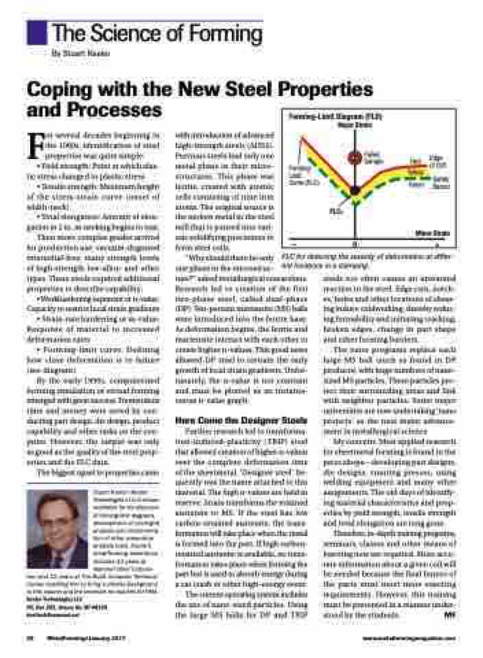
Forming-Limit Diagram (FLD) Major Strain
Forming- Limit
Curve (FLC)
FLC0
Failed Edge
Sample
Red of Cliff Yellow
Safety Green Barrier
Minor Strain
–0+
For several decades beginning in the 1960s, identification of steel properties was quite simple:
• Yield strength: Point at which elas- tic stress changed to plastic stress
• Tensile strength: Maximum height of the stress-strain curve (onset of width-neck)
• Total elongation: Amount of elon- gation in 2 in. as necking begins to tear. Then more complex grades arrived for production use: vacuum-degassed interstitial-free; many strength levels of high-strength low-alloy; and other types. These steels required additional
properties to describe capability:
• Workhardening exponent or n-value: Capacity to restrict local strain gradients • Strain-rate hardening or m-value: Response of material to increased
deformation rates
• Forming-limit curve: Defining
how close deformation is to failure (see diagram).
By the early-1990s, computerized forming simulation or virtual forming emerged with great success. Tremendous time and money were saved by con- ducting part design, die design, product capability and other tasks on the con- puter. However, the output was only as good as the quality of the steel prop- erties and the FLC data.
The biggest upset to properties came
Stuart Keeler (Keeler Technologies LLC) is known worldwide for his discovery of forming limit diagrams, development of circle-grid analysis and implementa- tion of other press-shop analysis tools. Keeler’s metalforming experience includes 24 years at National Steel Corpora-
tion and 12 years at The Budd Company Technical Center, enabling him to bring a diverse background to this column and the seminars he teaches for PMA. Keeler Technologies LLC
P.O. Box 283, Grosse Ile, MI 48138 keeltech@comcast.net
with introduction of advanced high-strength steels (AHSS). Previous steels had only one metal phase in their micro- structures. This phase was ferrite, created with atomic cells consisting of nine iron atoms. The original source is the molten metal in the steel mill that is poured into vari- ous solidifying processors to form steel coils.
“Why should there be only
one phase in the microstruc-
ture?” asked metallurgical researchers. Research led to creation of the first two-phase steel, called dual-phase (DP). Ten-percent martensite (MS) balls were introduced into the ferrite base. As deformation begins, the ferrite and martensite interact with each other to create higher n-values. This good news allowed DP steel to restrain the early growth of local strain gradients. Unfor- tunately, the n-value is not constant and must be plotted as an instanta- neous n-value graph.
Here Come the Designer Steels
Further research led to transforma- tion-induced-plasticity ( TRIP) steel that allowed creation of higher n-values over the complete deformation time of the sheetmetal. ‘Designer steel’ fre- quently was the name attached to this material. The high n-values are held in reserve. Strain transforms the retained austenite to MS. If the steel has low carbon-retained austenite, the trans- formation will take place when the metal is formed into the part. If high carbon- retained austenite is available, no trans- formation takes place when forming the part but is used to absorb energy during a car crash or other high-energy event.
The current operating system includes the use of nano-sized particles. Using the large MS balls for DP and TRIP
steels too often causes an unwanted reaction in the steel. Edge cuts, notch- es, holes and other locations of shear- ing induce coldworking, thereby reduc- ing formability and initiating cracking, broken edges, change in part shape and other forming barriers.
The nano programs replace each large MS ball (such as found in DP products) with huge numbers of nano- sized MS particles. These particles pro- tect their surrounding areas and link with neighbor particles. Some major universities are now undertaking ‘nano projects’ as the next major advance- ment in metallurgical science.
My concern: Most applied research for sheetmetal forming is found in the press shops—developing part designs, die designs, running presses, using welding equipment and many other assignments. The old days of identify- ing material characteristics and prop- erties by yield strength, tensile strength and total elongation are long gone.
Therefore, in-depth training programs, seminars, classes and other means of learning now are required. More accu- rate information about a given coil will be needed because the final buyers of the parts must meet more exacting requirements. However, this training must be presented in a manner under- stood by the students. MF
FLC for deterring the severity of deformation at differ- ent locations in a stamping.
38 MetalForming/January 2017
www.metalformingmagazine.com
