
Page 20 - MetalForming January 2017
P. 20
Optimizing Transfer-System Motion
bars and fingers go. Too often, he says, the press operator guesses at finger placement in the die; the trial-and-error method used to develop transfer timing just doesn’t cut it.
“When we run transfer-
tool simulations, often we’ll
look at several iterations of
bar and finger placement
until we find the best solution.
Then we provide that detail
to the stamper. This is just the beginning,” he says. “In addi-
tion, with our software we can calculate the optimum tim-
ing, based on preset limits for accel- eration and velocity, to add SPM. This means determining where to start and stop motion, and—most importantly —where we can overlap motion. Even a two or three additional strokes per minute can allow a stamper to free up enough press time to add one or two jobs to a press’s production lineup.”
Bottleneck Hunting
Where can bottlenecks be cleared and SPM optimized? It’s all in the pre- cise timing of the complex motion curves—clamp in, lift up, pitch forward, lift down, clamp out and pitch return. “Some of these bottlenecks kill pro- duction,” says Hansen. “These include travel distances and the time required to lift and clamp; pitch seems to typi- cally be well understood. So when we look at time bottlenecks, we focus on when can we clamp in, and how long do we have to wait for the upper tool to be out of the way to start the clamp- in motion. Then, we look at what in the upper tool is coming down, deter- mining when we have to clamp-out.
“Lift-up and pitch, and then lift- down are areas where we can overlap motion quite a bit in many cases, and alleviate a considerable bottleneck to add SPM,” he continues (see Fig. 1). “Stampers should pay close attention to opportunities to, for example, begin to pitch forward while still lifting up— look at the design of the tool for obsta- cles prohibiting an earlier start to the
18 MetalForming/January 2017
www.metalformingmagazine.com
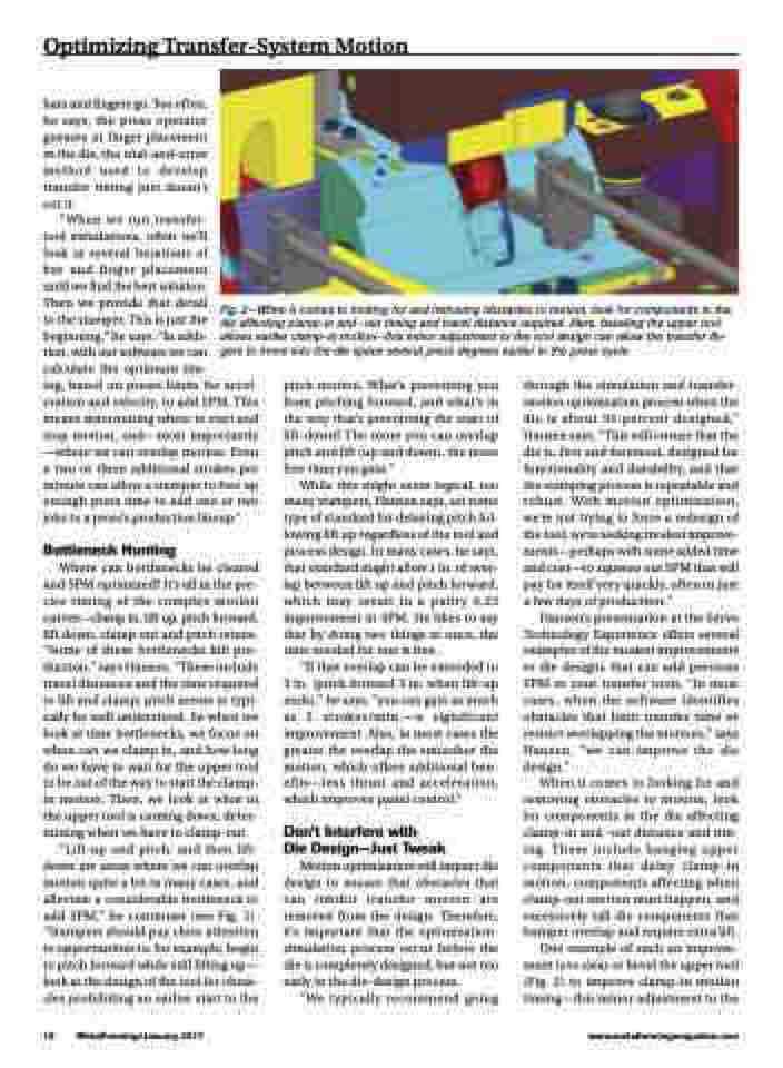
Fig. 2—When it comes to looking for and removing obstacles to motion, look for components in the die affecting clamp-in and -out timing and travel distance required. Here, beveling the upper tool allows earlier clamp-in motion—this minor adjustment to the tool design can allow the transfer fin- gers to move into the die space several press degrees earlier in the press cycle.
pitch motion. What’s preventing you from pitching forward, and what’s in the way that’s preventing the start of lift-down? The more you can overlap pitch and lift (up and down), the more free time you gain.”
While this might seem logical, too many stampers, Hansen says, set some type of standard for delaying pitch fol- lowing lift up regardless of the tool and process design. In many cases, he says, that standard might allow 1 in. of over- lap between lift up and pitch forward, which may result in a paltry 0.25 improvement in SPM. He likes to say that by doing two things at once, the time needed for one is free.
“If that overlap can be extended to 3 in. (pitch forward 3 in. when lift-up ends),” he says, “you can gain as much as 2 strokes/min.—a significant improvement. Also, in most cases the greater the overlap the smoother the motion, which offers additional ben- efits—less thrust and acceleration, which improves panel control.”
Don’t Interfere with
Die Design—Just Tweak
Motion optimization will impact die design to ensure that obstacles that can inhibit transfer motion are removed from the design. Therefore, it’s important that the optimization- simulation process occur before the die is completely designed, but not too early in the die-design process.
“We typically recommend going
through the simulation and transfer- motion optimization process when the die is about 95-percent designed,” Hansen says. “This will ensure that the die is, first and foremost, designed for functionality and durability, and that the stamping process is repeatable and robust. With motion optimization, we’re not trying to force a redesign of the tool; we’re seeking modest improve- ments—perhaps with some added time and cost—to squeeze out SPM that will pay for itself very quickly, often in just a few days of production.”
Hansen’s presentation at the Servo Technology Experience offers several examples of the modest improvements to die designs that can add precious SPM to your transfer tools. “In most cases, when the software identifies obstacles that limit transfer time or restrict overlapping the motions,” says Hansen, “we can improve the die design.”
When it comes to looking for and removing obstacles to motion, look for components in the die affecting clamp-in and -out distance and tim- ing. These include hanging upper components that delay clamp-in motion, components affecting when clamp-out motion must happen, and excessively tall die components that hamper overlap and require extra lift.
One example of such an improve- ment is to clear or bevel the upper tool (Fig. 2) to improve clamp-in motion timing—this minor adjustment to the
