
Page 38 - MetalForming August 2016
P. 38
The Science of Forming
By Stuart Keeler
Are Simulative Tests Still Useful?
Decades ago, simulative tests served as a main source of information defining how different metal alloys would survive forming operations based on part shape and complexity. Virtual forming-simulation software, computer-controlled tensile-test machines, lubricant eval- uators and other equipment used today were not available. Instead, small test devices were created, most of which were
can further reduce the allowable stretch.
To conduct an HET, the operator punches a hole into the
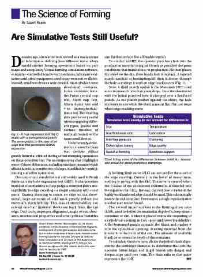
production material using (as closely as possible) the press conditions that match those in production. He then places the sheet on the die; draw beads lock it in place. A tapered punch (conical or hemispherical) then is driven through the hole to enlarge it until an edge crack occurs (Fig. 1).
Note: A third punch option is the Marciniak HET, used more in research labs than press shops. Here the sheetmetal with the initial punched hole is clamped over a flat-faced punch. As the punch pushes against the sheet, the hole increases in size while the sheet remains flat. The test stops when edge cracking starts.
Simulative Tests
Simulative tests usually do not account for differences in:
Size
Temperature
Size/thichness ratio
Lubrication
Interface pressure
Clamping
Deformation history
Edge quality
Speed of forming
Specimen support
Fig. 1—A hole expansion test (HET) made with a hemispherical punch. The arrow points to the start of an edge tear that terminates further expansion.
developed overseas. Some common tests: the Fukui conical cup test, Swift cup test, Olsen dome test and 4-in. hemispherical- dome test. The resulting data proved very useful when comparing differ- ent types, grades and surface finishes of materials tested on the same small device.
Unfortunately, defor- mation created by these test devices differs
greatly from that created during actual stamping operations on the production line. The accompanying chart highlights some of these differences, including interface pressure which affects lubricity, completion of shape, blankholder control, ironing and other operations.
One important simulative test still widely used in North America is the hole-expansion test (HET). It characterizes material stretchability to help judge a stamped part’s sus- ceptibility to edge cracking—a major concern with most parts. During shearing to create an edge on the sheet- metal, large amounts of cold work greatly reduce the material’s stretchability. This loss of stretchability can extend one-half material thickness back from the cut edge. Dull tools, improper alignment, angle of cut, clear- ance, mechanical properties and other process variables
Stuart Keeler (Keeler Technologies LLC) is known worldwide for his discovery of forming limit diagrams, development of circle-grid analysis and implementa- tion of other press-shop analysis tools. Keeler’s metal- forming experience includes 24 years at National Steel Corporation and 12 years at The Budd Compa- ny Technical Center, enabling him to bring a very diverse background to this column and to the semi- nars he teaches for PMA.
Keeler Technologies LLC
P.O. Box 283 | Grosse Ile, MI 48138 keeltech@comcast.net
Chart listing some of the differences between small test devices and actual full-sized production stampings.
A forming-limit curve (FLC) cannot predict the onset of the edge cracking. Contrary to the belief of many users, nothing is wrong with the FLC. The error is created when the n-value of the as-received sheetmetal is inserted into the equation for FLC0. Instead, the very low n-value in the highly workhardened edge should be used. This substantially lowers the red-zone line. Even worse, a single representative n-value may not be found.
The second important test is the limiting draw ratio (LDR), used to define the maximum depth of a deep-drawn container or can. A blank is placed over a die consisting of a cylindrical opening and an upper and lower blankholder. A flat-bottomed punch contacts the blank and pushes it into the cylindrical opening, drawing material from the binder into the body of the can. The amount of available blank determines the depth of the container.
To calculate the draw ratio, divide the initial blank diam- eter by the container diameter. To determine the LDR, the operator forms larger and larger blanks into deeper and deeper cups until one tears. The draw ratio at that point represents the LDR. MF
36 MetalForming/August 2016
www.metalformingmagazine.com
