
Page 34 - MetalForming April 2016
P. 34
Programming for 3D Laser Cutting
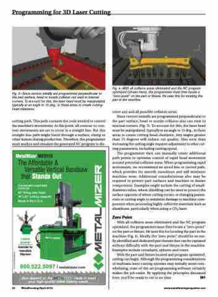
Fig. 3—Since vectors initially are programmed perpendicular to the part surface, head or nozzle collision can exist in internal corners. To account for this, the laser head must be manipulated, typically at an angle to 15 deg., in these areas to create cutting- head clearance.
cutting path. This path contains the code needed to control the machine’s movements. At this point, all contour-to-con- tour movements are set to occur in a straight line. But this straight-line path might travel through a surface, clamp or other feature during production. Therefore, the programmer must analyze and simulate the generated NC program to dis-
Fig. 4—With all collision areas eliminated and the NC program optimized (shown here), the programmer must then locate a “zero-point” on the part or fixture. He uses this for locating the part in the machine.
cover any and all possible collision areas.
Since vectors initially are programmed perpendicular to
the part surface, head or nozzle collision also can exist in internal corners (Fig. 3). To account for this, the laser head must be manipulated, typically at an angle to 15 deg., in these areas to create cutting-head clearance. Any angles greater than 15 degrees will reduce cut quality. Also note than increasing the cutting angle requires adjustment to other cut- ting parameters, including cutting speed.
The programmer then can manually create additional path points to optimize control of rapid head movement around potential collision areas. When programming rapid movements, we recommend an arced line or curved path, which provides for smooth transitions and will minimize machine wear. Additional considerations also may be required to protect part surfaces and machine or fixture components. Examples might include the cutting of small- diameter tubes, where shielding can be used to protect the surface opposite of where cutting occurs; or changing param- eters or cutting angle to minimize damage to machine com- ponents when processing highly-reflective materials such as aluminum, particularly when using a CO2 laser.
Zero Point
With all collision areas eliminated and the NC program optimized, the programmer must then locate a “zero-point” on the part or fixture. He uses this for locating the part in the machine (Fig. 4). Ideally, the “zero-point” should be an eas- ily identified and dedicated part feature that can be captured without difficulty with the part and fixture in the machine. Examples include crosshairs, spheres and cones.
With the part and fixture located and program optimized, cutting can begin. Although the programming considerations of multiaxis laser-cutting systems may initially seem over- whelming, state-of-the-art programming software certainly makes the job easier. By applying the principles discussed here, you’ll be ready to cut in no time. MF
MetalMizer MV2018 The Affordable &
Versatile Vertical Bandsaw that Stands Out
• Convenient overhead controls
• 45° tilting saw head
• 18"x20"cutting capacity
• Made in the U.S.A.
Limited Quantity!
Available for Immediate Shipment
800.522.5097 metalmizer.com
Also depend on the
your high-quality metal sawing needs.
METALFLEX blade to meet
32 MetalForming/April 2016
www.metalformingmagazine.com
© 2016 MetalMizer
