
Page 33 - MetalForming April 2016
P. 33
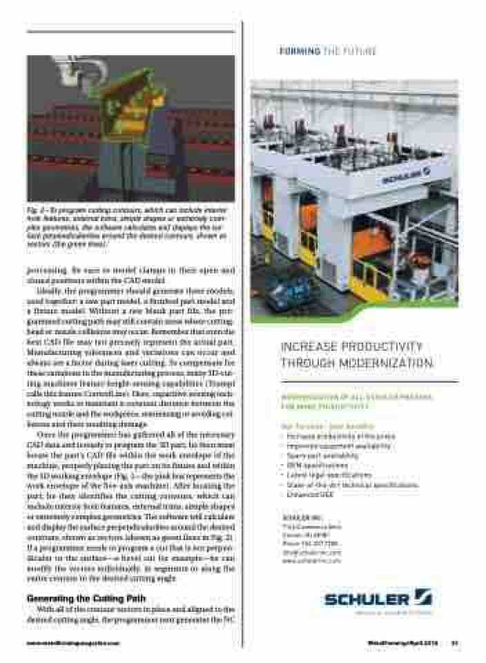
Fig. 2—To program cutting contours, which can include interior hole features, external trims, simple shapes or extremely com- plex geometries, the software calculates and displays the sur- face perpendicularities around the desired contours, shown as vectors (the green lines).
processing. Be sure to model clamps in their open and closed positions within the CAD model.
Ideally, the programmer should generate three models, used together: a raw part model, a finished part model and a fixture model. Without a raw blank part file, the pro- grammed cutting path may still contain areas where cutting- head or nozzle collisions may occur. Remember that even the best CAD file may not precisely represent the actual part. Manufacturing tolerances and variations can occur and always are a factor during laser cutting. To compensate for these variations in the manufacturing process, many 3D-cut- ting machines feature height-sensing capabilities (Trumpf calls this feature ControlLine). Here, capacitive sensing tech- nology works to maintain a constant distance between the cutting nozzle and the workpiece, minimizing or avoiding col- lisions and their resulting damage.
Once the programmer has gathered all of the necessary CAD data and is ready to program the 3D part, he then must locate the part’s CAD file within the work envelope of the machine, properly placing the part on its fixture and within the 3D working envelope (Fig. 1—the pink box represents the work envelope of the five-axis machine). After locating the part, he then identifies the cutting contours, which can include interior hole features, external trims, simple shapes or extremely complex geometries. The software will calculate and display the surface perpendicularities around the desired contours, shown as vectors (shown as green lines in Fig. 2). If a programmer needs to program a cut that is not perpen- dicular to the surface—a bevel cut for example—he can modify the vectors individually, in segments or along the entire contour to the desired cutting angle.
Generating the Cutting Path
With all of the contour vectors in place and aligned to the desired cutting angle, the programmer next generates the NC
INCREASE PRODUCTIVITY THROUGH MODERNIZATION.
MODERNIZATION OF ALL SCHULER PRESSES FOR MORE PRODUCTIVITY.
Our Services - your benefits:
� Increase productivity of the press � Improved equipment availability
� Spare part availability
� OEM specifications
� Latest legal specifications
� State-of-the-Art technical specifications � Enhanced OEE
SCHULER INC.
7145 Commerce Blvd. Canton, MI 48187 Phone 734.207.7200 info@schulerinc.com www.schulerinc.com
www.metalformingmagazine.com
MetalForming/April 2016 31
