
Page 28 - MetalForming August 2015
P. 28
Automating Die Design
Parametric software, on the other hand, allows for relationships within the assembly from one part to the next, forming what can be called intelligence. These relationships are created by users who know their final goals as they design dies. This is known as design intent. Both the parametric CAD soft- ware as well its add-on software help manage the creation and editing of these relationships. Simply put, many different parameters can be set in this software, and once the user sets param- eters for a project, he presses a button that allows the software to perform the heavy lifting.
Add-On Software
Tackles Specific Challenges
A 3D CAD package by itself, such as the SolidWorks software recently added by Wisconsin Metal Parts, is sim- ilar to a family doctor in that just as a doctor sees many different patients and treats a variety of illnesses, so, too, is the CAD software package used by people in a variety of industries design- ing vastly different things. But in the case of a family doctor, he calls a spe- cialist for something very specific and complex, such as a patient requiring heart surgery. Likewise, 3D die-design software packages are specifically designed to address and streamline the nuances unique to die design.
While Wisconsin Metal Parts saw many benefits over its previous soft-
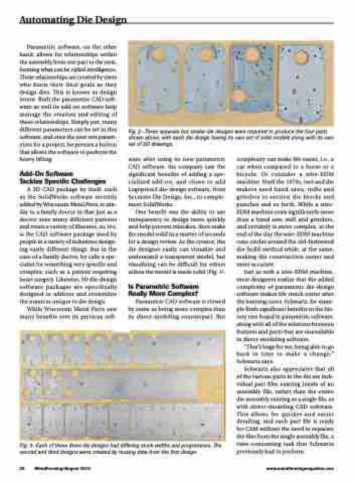
Fig. 2—Three separate but similar die designs were required to produce the four parts shown above, with each die design having its own set of solid models along with its own set of 2D drawings.
ware after using its new parametric CAD software, the company saw the significant benefits of adding a spe- cialized add-on, and chose to add Logopress3 die-design software, from Accurate Die Design, Inc., to comple- ment SolidWorks.
One benefit was the ability to use transparency to design more quickly and help prevent mistakes, then make the model solid in a matter of seconds for a design review. As the creator, the die designer easily can visualize and understand a transparent model, but visualizing can be difficult for others unless the model is made solid (Fig. 1).
Is Parametric Software Really More Complex?
Parametric CAD software is viewed by some as being more complex than its direct-modeling counterpart. But
complexity can make life easier, i.e., a car when compared to a horse or a bicycle. Or consider a wire-EDM machine. Until the 1970s, tool and die makers used band saws, mills and grinders to section die blocks and punches and so forth. While a wire- EDM machine costs significantly more than a band saw, mill and grinders, and certainly is more complex, at the end of the day the wire-EDM machine runs circles around the old-fashioned die-build method while, at the same, making die construction easier and more accurate.
Just as with a wire-EDM machine, most designers realize that the added complexity of parametric die-design software makes life much easier after the learning curve. Schwartz, for exam- ple finds significant benefits in the his- tory tree found in parametric software, along with all of the relations between features and parts that are unavailable in direct-modeling software.
“That’s huge for me, being able to go back in time to make a change,” Schwartz says.
Schwartz also appreciates that all of the various parts in the die are indi- vidual part files existing inside of an assembly file, rather than the entire die assembly existing as a single file, as with direct-modeling CAD software. This allows for quicker and easier detailing, and each part file is ready for CAM without the need to separate the files from the single assembly file, a time-consuming task that Schwartz previously had to perform.
Fig. 3—Each of these three die designs had differing stock widths and progressions. The second and third designs were created by reusing data from the first design.
26 MetalForming/August 2015
www.metalformingmagazine.com
