
Page 26 - MetalForming August 2015
P. 26
Automating Die Design
Dan Erschen established Die Concepts, Inc. as a die-design business in 1988. Within a few years the company branched out, per- forming custom machining along with providing dies for stampers and OEMs. By 2010 it was time for a name change to better describe the business, so Die Concepts, Inc. became Wisconsin Metal Parts, Inc. Today, the Waukesha, WI, company manufactures assemblies and metal parts, specializing in stamping, die making, sheetmetal fabrication and CNC machining.
In 2003, having used AutoCAD along with an add-on die-design software for several years, the company decided to
Ray Proeber is president of Accurate Die Design, Inc., New Berlin, WI; www.accu- ratediedesign.com.
—a Case Study
Wisconsin Metal Parts switches to 3D die-design software that employs parametric modeling. The result: quicker die design with fewer mistakes made during the process.
BY RAY PROEBER
move into 3D die design. It purchased two seats of a 3D die-design software package that employs direct-model- ing technology, and had two designers trained in its use. For the next 10 years Erschen’s business used the software to design many dies, but eventually moved back to 2D die-design software for jobs not requiring 3D modeling. One reason why, as die designer Bill Schwartz says: “We were getting absolutely killed on design hours.”
In 2014, Wisconsin Metal Parts again
switched, this time to 3D die-design software that uses parametric-modeling technology, and six months later added a die-design add-on software package.
This example represents the overall results: Schwartz recently found himself needing to add 48 punches to a die design, including spacers behind the punches, die buttons and all related holes in the various plates in the die. After he set the parameters in the die- design software to perform this task, but before clicking the okay button, Schwartz decided to time the process.
“I was amazed that 1 min. and 45 sec. was all the time it took for the software to perform
all of this work,” he recalls.
Direct Modeling Versus Parametric
The geometry creat- ed with direct-model- ing software can be
referred to as “dumb” geometry because it lacks the intelligence relating to other geometry in the assem- bly, as is the case with parametric software. This limits the level of automation achievable via direct-
modeling software.
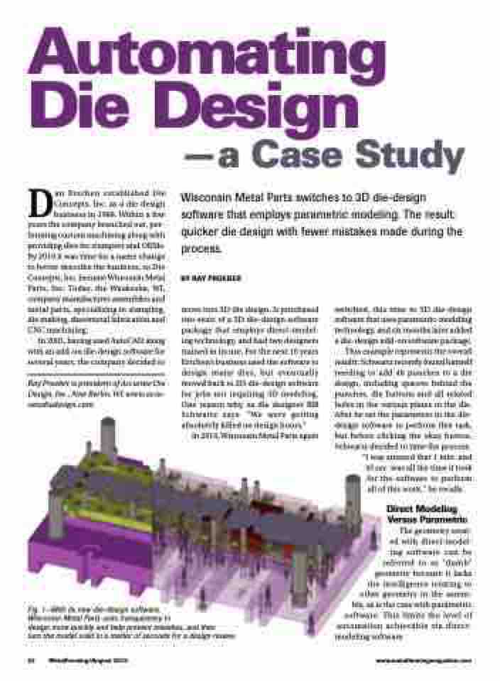
Fig. 1—With its new die-design software,
Wisconsin Metal Parts uses transparency to
design more quickly and help prevent mistakes, and then
turn the model solid in a matter of seconds for a design review.
24 MetalForming/August 2015
www.metalformingmagazine.com
