
Page 46 - MetalForming May 2015
P. 46
What’s New in Die Design and Simulation Software
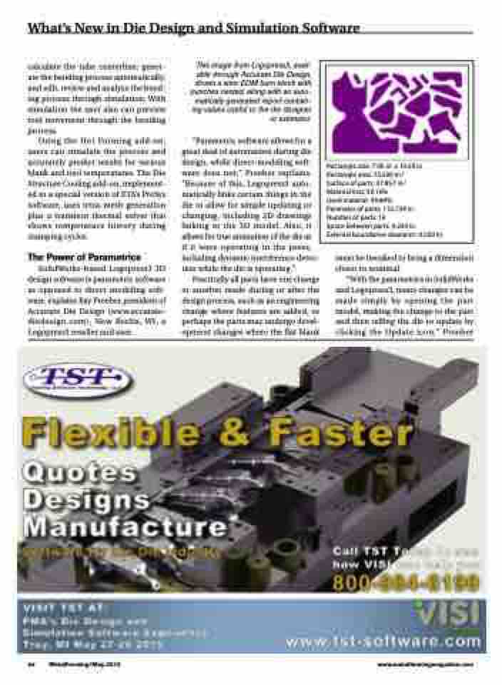
Rectangle size: 7.00 in. x 10.50 in. Rectangle area: 73.500 in.2 Surface of parts: 37.857 in.2 Material loss: 50.16%
Used material: 49.84%
Perimeter of parts: 112.734 in.
Number of parts: 16
Space between parts: 0.250 in.
External boundaries clearance: 0.500 in.
calculate the tube centerline; gener- ate the bending process automatically; and edit, review and analyze the bend- ing process through simulation. With simulation the user also can preview tool movement through the bending process.
Using the Hot Forming add-on, users can simulate the process and accurately predict results for various blank and tool temperatures. The Die Structure Cooling add-on, implement- ed in a special version of ETA’s PreSys software, uses tetra-mesh generation plus a transient thermal solver that shows temperature history during stamping cycles.
The Power of Parametrics
SolidWorks-based Logopress3 3D design software is parametric software as opposed to direct modeling soft- ware, explains Ray Proeber, president of Accurate Die Design (www.accurate- diedesign.com), New Berlin, WI, a Logopress3 reseller and user.
This image from Logopress3, avail- able through Accurate Die Design, shows a wire-EDM burn block with punches nested, along with an auto- matically generated report contain- ing values useful to the die designer or estimator.
“Parametric software allows for a great deal of automation during die design, while direct-modeling soft- ware does not,” Proeber explains. “Because of this, Logopress3 auto- matically links certain things in the die to allow for simple updating or changing, including 2D drawings linking to the 3D model. Also, it allows for true animation of the die as
if it were operating in the press, including dynamic interference detec- tion while the die is operating.”
Practically all parts have one change or another made during or after the design process, such as an engineering change where features are added, or perhaps the parts may undergo devel- opment changes where the flat blank
must be tweaked to bring a dimension closer to nominal.
“With the parametrics in SolidWorks and Logopress3, many changes can be made simply by opening the part model, making the change to the part and then telling the die to update by clicking the Update icon,” Proeber
44 MetalForming/May 2015
www.metalformingmagazine.com
