
Page 40 - MetalForming May 2015
P. 40
Optimize Aluminum-Welding Performance
From Shavings to Savings
Just as there’s a performance difference between conventional, pulsed and modified pulsed-spray welding, there’s a performance difference between standard and premium filler metals. In the case of aluminum wire, conventional 5xxx-series wires have a well- deserved reputation for generating aluminum wire shavings that build up in the wire- feeder drive rolls, liner and contact tip. As the shavings build up, they hinder feeding performance, create excessive consumable wear, cause more frequent burnbacks and increase the need for routine maintenance.
Even worse, the problem creates a vicious circle: As aluminum particles flake off and embed in the gun liner, they score the wire and create additional shavings. Over- tensioning the drive rolls generates shavings, as does wire-to-wire scuffing, but the problem used to be inherent in the product.
To address this issue, a new weld-wire manufacturing process (from AlcoTec) elimi- nates the microfines and surface abrasion generated during wire drawing. This mini- mizes or eliminates the shaving problem, greatly improving wire feedability and arc sta- bility. These improvements result in less wear and tear on contact tips and less frequent replacement of liners.
machine might have synergic lines for the following grades of aluminum filler wire: 5356, 5183, 5556, 5554, 4043, 4047 and 1100. The human-machine inter- face prompts users to select and enter process variables such as shielding gas and wire type and diameter, and then select the desired welding process. Once entered, the welding machine (power supply and wire feeder) auto- matically determines process variables and delivers optimized arc perform- ance with no advanced-process knowl- edge required.
To increase or decrease travel speed, operators simply adjust wire-feed speed accordingly. The power supply automatically adjusts all other process variables to maintain optimum arc conditions. This type of control, called “synergic control,” finds use in many of today’s advanced power supplies.
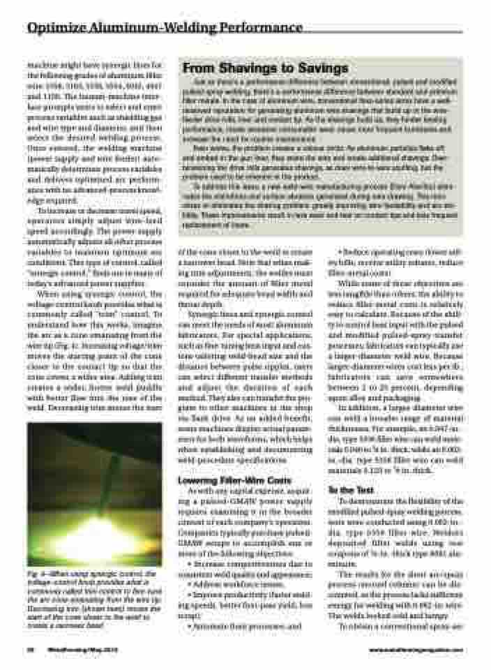
When using synergic control, the voltage-control knob provides what is commonly called “trim” control. To understand how this works, imagine the arc as a cone emanating from the wire tip (Fig. 4). Increasing voltage/trim moves the starting point of the cone closer to the contact tip so that the cone covers a wider area. Adding trim creates a wider, hotter weld puddle with better flow into the toes of the weld. Decreasing trim moves the start
Fig. 4—When using synergic control, the voltage-control knob provides what is commonly called trim control to fine-tune the arc cone emanating from the wire tip. Decreasing trim (shown here) moves the start of the cone closer to the weld to create a narrower bead.
of the cone closer to the weld to create a narrower bead. Note that when mak- ing trim adjustments, the welder must consider the amount of filler metal required for adequate bead width and throat depth.
Synergic lines and synergic control can meet the needs of most aluminum fabricators. For special applications, such as fine-tuning heat input and cus- tom-tailoring weld-bead size and the distance between pulse ripples, users can select different transfer methods and adjust the duration of each method. They also can transfer the pro- gram to other machines in the shop via flash drive. As an added benefit, some machines display actual param- eters for both waveforms, which helps when establishing and documenting weld-procedure specifications.
Lowering Filler-Wire Costs
As with any capital expense, acquir- ing a pulsed-GMAW power supply requires examining it in the broader context of each company’s operation. Companies typically purchase pulsed- GMAW setups to accomplish one or more of the following objectives:
• Increase competitiveness due to consistent weld quality and appearance;
• Address workforce issues;
• Improve productivity (faster weld- ing speeds, better first-pass yield, less scrap);
• Automate their processes; and
• Reduce operating costs (lower util- ity bills, receive utility rebates, reduce filler-metal costs).
While some of these objectives are less tangible than others, the ability to reduce filler-metal costs is relatively easy to calculate. Because of the abili- ty to control heat input with the pulsed and modified pulsed-spray transfer processes, fabricators can typically use a larger-diameter weld wire. Because larger-diameter wires cost less per lb., fabricators can save somewhere between 2 to 25 percent, depending upon alloy and packaging.
In addition, a larger-diameter wire can weld a broader range of material thicknesses. For example, an 0.047-in.- dia. type 5356 filler wire can weld mate- rials 0.040 to 3⁄8 in. thick, while an 0.062- in.-dia. type 5356 filler wire can weld materials 0.125 to 5⁄8 in. thick.
To the Test
To demonstrate the flexibility of the modified pulsed-spray welding process, tests were conducted using 0.062-in.- dia. type 5356 filler wire. Welders deposited fillet welds using test coupons of 1⁄8-in.-thick type 6061 alu- minum.
The results for the short arc/spray process (second column) can be dis- counted, as the process lacks sufficient energy for welding with 0.062-in. wire. The welds looked cold and lumpy.
To obtain a conventional spray-arc
38 MetalForming/May 2015
www.metalformingmagazine.com
