
Page 62 - MetalForming April 2015
P. 62
Tooling by Design
By Peter Ulintz
Die-Set Guiding Systems
The upper and lower halves of a stamping die must be accurately aligned and guided throughout their working distance to ensure that they perform as designed. Many dies rely solely on guide posts and bushings; others may use wear plates or a com- bination of wear plates and guide posts to align the upper punch and the lower die assembly.
Two basic types of guide-post and bushing systems are available:
Plain-bearing post and bushing arrangements are commercially avail- able in either pressed-in or demount- able designs. The guide post is usual- ly—but not always—mounted to the lower die half. It will be long enough to ensure adequate engagement with the guide bushing, which is mounted in the opposite half of the die assembly, during initial contact between the tool- ing and the workpiece.
Plain-bearing bushings are avail- able in several different materials, with bronze-plated steel or solid-aluminum bronze—with or without self-lubricat- ing graphite—being most common. The post and bushing arrangement is designed with a small amount of run- ning clearance between the post and bushing.
Peter Ulintz has worked in the metal stamping and tool and die indus- tries since 1978. He has been employed with the Anchor Manufacturing Group in Cleveland, OH, since 1989. His back- ground includes tool and die making, tool engi- neering, process engi-
neering, engineering management and product development. Peter speaks regularly at PMA semi- nars and conferences. He is also vice president of the North American Deep Drawing Research Group. Peter Ulintz
pete.ulintz@toolingbydesign.com www.toolingbydesign.com
A ballbearing
guide-post and
bushing combina-
tion is the second
type of system.
Ballbearing guide
components work
in a preloaded con-
dition with a rolling
press-fit or nega-
tive clearance.
These components
simplify assembly
and disassembly of
long progressive
die sets. However, when the stamping process produces excessive side-load- ing on a tool, ballbearing guide com- ponents may not be the best option. These side loads transfer to individual ballbearings that are in point-contact (tangent to the ball diameter) with the post and bushing. As a result, the balls can dig tracking marks into the guide- post OD or bushing ID.
Important Considerations for Post-Guided Systems
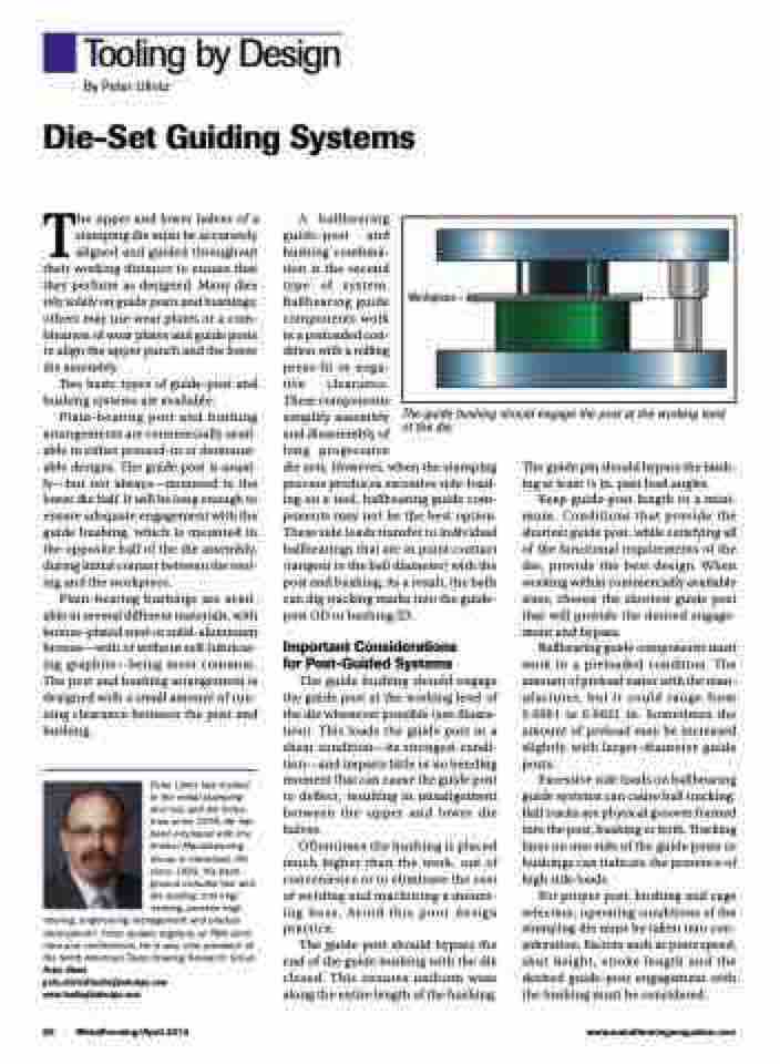
The guide bushing should engage the guide post at the working level of the die whenever possible (see illusra- tion). This loads the guide post in a shear condition—its strongest condi- tion—and imparts little or no bending moment that can cause the guide post to deflect, resulting in misalignment between the upper and lower die halves.
Oftentimes the bushing is placed much higher than the work, out of convenience or to eliminate the cost of welding and machining a mount- ing boss. Avoid this poor design practice.
The guide post should bypass the end of the guide bushing with the die closed. This ensures uniform wear along the entire length of the bushing.
Workpiece
The guide bushing should engage the post at the working level of the die.
The guide pin should bypass the bush- ing at least 1⁄4 in. past lead angles.
Keep guide-post length to a mini- mum. Conditions that provide the shortest guide post, while satisfying all of the functional requirements of the die, provide the best design. When working within commercially available sizes, choose the shortest guide post that will provide the desired engage- ment and bypass.
Ballbearing guide components must work in a preloaded condition. The amount of preload varies with the man- ufacturer, but it could range from 0.0001 to 0.0021 in. Sometimes the amount of preload may be increased slightly with larger-diameter guide posts.
Excessive side loads on ballbearing guide systems can cause ball tracking. Ball tracks are physical grooves formed into the post, bushing or both. Tracking lines on one side of the guide posts or bushings can indicate the presence of high side loads.
For proper post, bushing and cage selection, operating conditions of the stamping die must be taken into con- sideration. Factors such as press speed, shut height, stroke length and the desired guide-post engagement with the bushing must be considered.
60 MetalForming/April 2015
www.metalformingmagazine.com
