
Page 30 - MetalForming February 2015
P. 30
CAD Efficiency
A
“Now we have one die guy and two mold designers. So, we’re twice as productive and the work flow is greatly enhanced.” The improved work flow shows itself not just in the engi- neering office but also out on the shop floor, where Jamesway’s tool builders and machinists work. A pair of CAD viewing stations (powered by Cimatron) on the plant floor provide visual tools to help guide the tool builders, a sig- nificantly more powerful instructional aid compared to 2D
prints.
“The viewing stations let our operators view the 3D die-
section and component models, and cut sections to enhance their visualization when evaluating the manufacturing- process instructions,” says Gortsema. “This provides a much more efficient build process, and eliminates much of the need for the builders to seek out designers with questions should any instructions initially be unclear.”
Enhanced visualization of the developed tool sections also greatly improves communications with customers. “Now we can send actual, virtual strip layouts to them,” says Roze- boom. “This streamlines the back-and forth communication process between our engineers and theirs, to fine-tune the die design as needed.”
More Efficient, More Competitive Quotes
Jamesway also uses its one-stop die-development solution to optimize quoting speed and accuracy, and improve its abil- ity to take on more complex jobs. “Not that we used to shy away from complex work,” says Dave Rozeboom, Mark’s brother and the company’s president, “but now our quotes are much more competitive on these types of jobs.”
He should know, since he handles much of the firm’s die quotes. “Before we adopted Cimatron on the die side of the business,” he continues, “we might have had to occasional- ly quote higher than we wanted to when we weren’t sure we could properly execute the job. Now, with the new software we can more accurately and confidently develop blanks, determine the number of progressions and progression pitch, and other details.”
For example, late in 2014 the firm received two large orders at once, 20 projects in all, comprising progressive dies for stamping a group of seating parts for the automotive industry, and tooling to stamp ATV roll-bar assemblies. Gortsema points to one of the seat parts as particularly challenging and says that “without the ability to design in 3D using Cimatron, we may not have been able to win the proj- ect at all.”
The part in question is small and complex—a two-out die that makes 3- by 4-in. parts separated by just a 3⁄4-in. web. Challenging to the tool-design and build process were the number of small, intricate and multifaceted forming process- es required, and the call for cam piercing on both sides of each part.
“The software really helped us visualize all of that work happening in a small amount of available space,” Gortsema says. “When the parts are larger they’re typically easier to deal
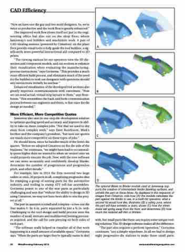
The optional Blank on Binder module used at Jamesway sup- ports the creation of intermediate binder blanking surfaces, and unfolds the part on these faces. As displayed in this sequence of images from Cimatron, note how (A) the module calculates the part against the binder to see, in a multi-hit operation, what a second hit would look like; illustrates (B) a safety zone, where the part will have wrinkles or tears; shows (C) how the sheet- metal will spring away from the form; and determines (D) how much the material will thin or thicken.
with, but small parts like these can require some unique tool- ing solutions. The 3D design software makes all the difference. “The part also requires a preform operation,” Gortsema continues, “not a simple wipedown. In all we had to design eight progressive-die stations to make those small parts.
B
C
D
28 MetalForming/February 2015
www.metalformingmagazine.com
