
Page 46 - MetalForming September 2014
P. 46
������� �������� ��� ����� � ������
����� ����� ������ ��� ��������
�������� �� ������ ��� ����� ��������
���� ����� ����� ��������
����� ����� ���������� �������� ���� ���������� �������
������������� ����� ��������
������ ���� ���������� �������� ����������
����� ����� ������ � ��������
������ ����� �������� ������ ��� �������
��������� ���� �������
���� � ���� ��������� ��������
����� ������� � ���� ����������
���� �� ��� ���
������������ ������������������������������ ����������������������������
The Science of Forming
2.0
1.0
0.0
Pulling Load (Pp) Strip Travel
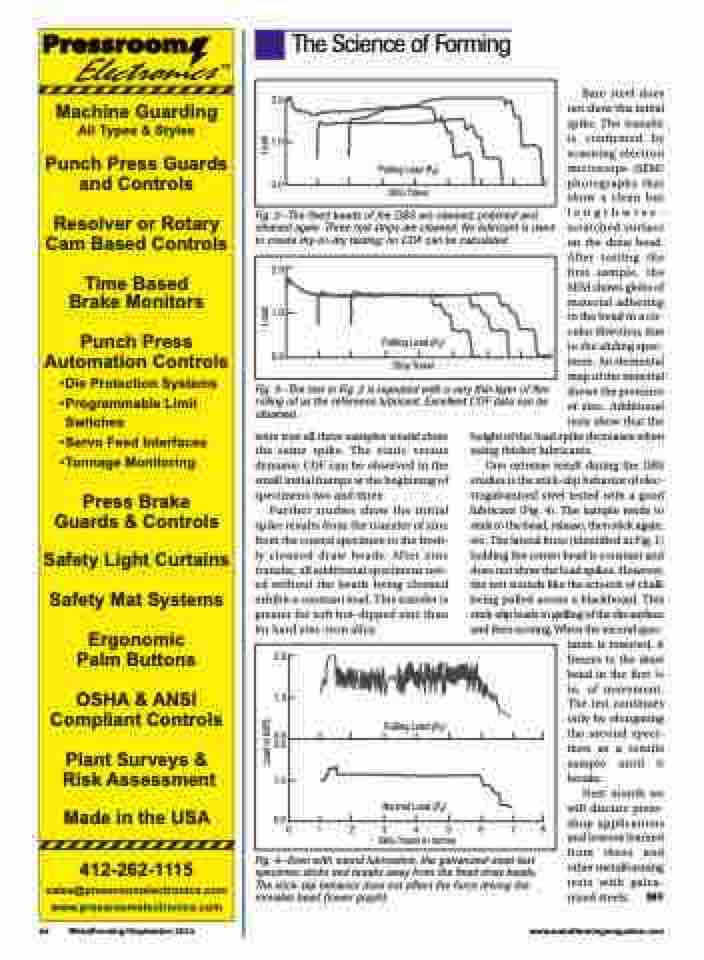
Fig. 2—The fixed beads of the DBS are cleaned, polished and cleaned again. Three test strips are cleaned. No lubricant is used to create dry-to-dry testing; no COF can be calculated.
Fig. 3—The test in Fig. 2 is repeated with a very thin layer of flex rolling oil as the reference lubricant. Excellent COF data can be obtained.
Bare steel does not show this initial spike. The transfer is confirmed by scanning electron microscope (SEM) photographs that show a clean but lengthwise- scratched surface on the draw bead. After testing the first sample, the SEM shows globs of material adhering to the bead in a cir- cular direction, due to the sliding spec- imen. An elemental map of the material shows the presence of zinc. Additional tests show that the
2.0
1.0
0.0
Pulling Load (Pp) Strip Travel
were true all three samples would show the same spike. The static versus dynamic COF can be observed in the small initial humps at the beginning of specimens two and three.
Further studies show the initial spike results from the transfer of zinc from the coated specimen to the fresh- ly cleaned draw beads. After zinc transfer, all additional specimens test- ed without the beads being cleaned exhibit a constant load. This transfer is greater for soft hot-dipped zinc than for hard zinc-iron alloy.
height of the load spike decreases when using thicker lubricants.
One extreme result during the DBS studies is the stick-slip behavior of elec- trogalvanized steel tested with a good lubricant (Fig. 4). The sample tends to stick to the bead, release, then stick again, etc. The lateral force (identified in Fig. 1) holding the center bead is constant and does not show the load spikes. However, the test sounds like the screech of chalk being pulled across a blackboard. This stick-slip leads to galling of the die surface and then scoring. When the second spec-
imen is inserted, it freezes to the draw bead in the first 1⁄4 in. of movement. The test continues only by elongating the second speci- men as a tensile sample until it breaks.
Next month we will discuss press- shop applications and lessons learned from these and other metalforming tests with galva-
2.0
1.0
0.0 2.0
1.0
Pulling Load (Pp)
Normal Load (Pn)
0.0 012345678
Strip Travel in inches
44 MetalForming/September 2014
www.metalformingmagazine.com
Fig. 4—Even with sound lubrication, the galvanized-steel test
specimen sticks and breaks away from the fixed draw beads.
The stick-slip behavior does not affect the force driving the
movable bead (lower graph). nized steels. MF
Load in KIPS
Load Load
