
Page 45 - MetalForming September 2014
P. 45
The Science of Forming By Stuart Keeler
Galvanized Coating Changes Steel Formability
Guide Rollers
Variable
BHd+f (Lateral-Force)
μ=
DRf
(π) BHd+f
DRd+f
(Pull Force)
= DRd+f–DRd (π) BHd+f
Most draw dies require a critical balance between stretching sheetmetal over the punch shape and allowing the blank to flow into the die cavity. For complex-shaped stamp- ings, the restraint on material flow into the die cavity can vary greatly around the circumference of the stamping.
Draw beads and blank shape repre- sent the primary modes of flow control. The three principal variables: work- piece-material surface topography, coating and lubricant. Most bare (uncoated) steel ships from the mill with a lubricant already applied, from a simple rust-protective oil to a special low-friction lubricant. In addition, the mill typically performs a final temper pass on cold-rolled steel before ship- ment, which imparts a surface rough- ness and peak count within specified limits. This allows the press shop to utilize the steel with some degree of reproducibility from run to run.
Now imagine that one day your press shop receives instructions to pro- duce stampings from galvanized steel, replacing the existing bare steel. What friction changes will be encountered? Can the process be stabilized?
To answer some of these questions, a draw-bead simulator (DBS, Fig. 1)
Stuart Keeler (Keeler Technologies LLC) is known worldwide for his discovery of forming limit diagrams, development of circle-grid analysis and implementation of other press-shop analysis
tools. Keeler’s metalform- ing experience includes 24 years at National
Steel Corporation and 12 years at The Budd Com- pany Technical Center, enabling him to bring a very diverse background to this column and to the sem- inars he teaches for PMA.
Keeler Technologies LLC
P.O. Box 283, Grosse Ile, MI 48138 Fax: 734/671-2271 keeltech@comcast.net
was built using a design developed by Dr. Harmon Nine of GM Research. Three fixed draw beads duplicate the condi- tions of an actual draw bead around which the sheetmetal is drawn. The DBS beads are cleaned with a degreaser, abraded with 600-grit SiC paper, and then cleaned again with the degreaser before each friction evaluation.
We use the DBS to
conduct two sets of
tests for each material/
lubricant combination.
We begin by pulling
three identical strips
of material through
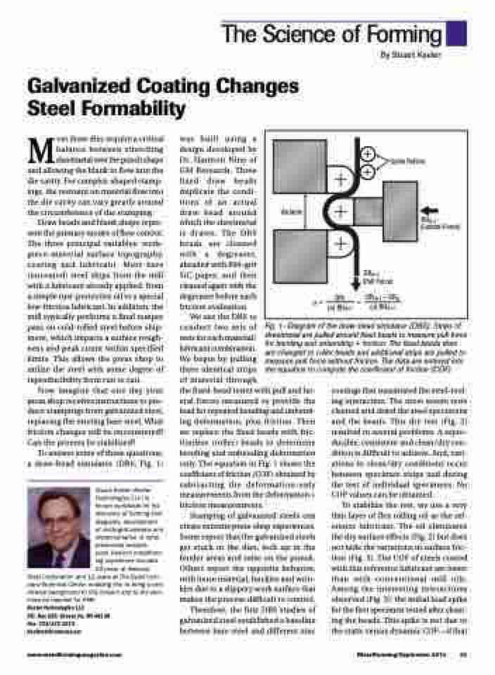
the fixed-bead tester with pull and lat- eral forces measured to provide the load for repeated bending and unbend- ing deformation, plus friction. Then we replace the fixed beads with fric- tionless (roller) beads to determine bending and unbending deformation only. The equation in Fig. 1 shows the coefficient of friction (COF) obtained by subtracting the deformation-only measurements from the deformation + friction measurements.
Stamping of galvanized steels can create extreme press-shop experiences. Some report that the galvanized steels get stuck in the dies, lock up in the binder areas and seize on the punch. Others report the opposite behavior, with loose material, buckles and wrin- kles due to a slippery work surface that makes the process difficult to control.
Therefore, the first DBS studies of galvanized steel established a baseline between bare steel and different zinc
Fig. 1—Diagram of the draw-bead simulator (DBS). Strips of sheetmetal are pulled around fixed beads to measure pull force for bending and unbending + friction. The fixed beads then are changed to roller beads and additional strips are pulled to measure pull force without friction. The data are entered into the equation to compute the coefficient of friction (COF).
coatings that maximized the steel-tool- ing interaction. The most severe tests cleaned and dried the steel specimens and the beads. This dry test (Fig. 2) resulted in several problems. A repro- ducible, consistent and clean/dry con- dition is difficult to achieve. And, vari- ations in clean/dry conditions occur between specimen strips and during the test of individual specimens. No COF values can be obtained.
To stabilize the test, we use a very thin layer of flex rolling oil as the ref- erence lubricant. The oil eliminates the dry surface effects (Fig. 2) but does not hide the variations in surface fric- tion (Fig. 3). The COF of steels coated with this reference lubricant are lower than with conventional mill oils. Among the interesting interactions observed (Fig. 3): the initial load spike for the first specimen tested after clean- ing the beads. This spike is not due to the static versus dynamic COF—if that
www.metalformingmagazine.com
MetalForming/September 2014 43
