
Page 35 - MetalForming August 2014
P. 35
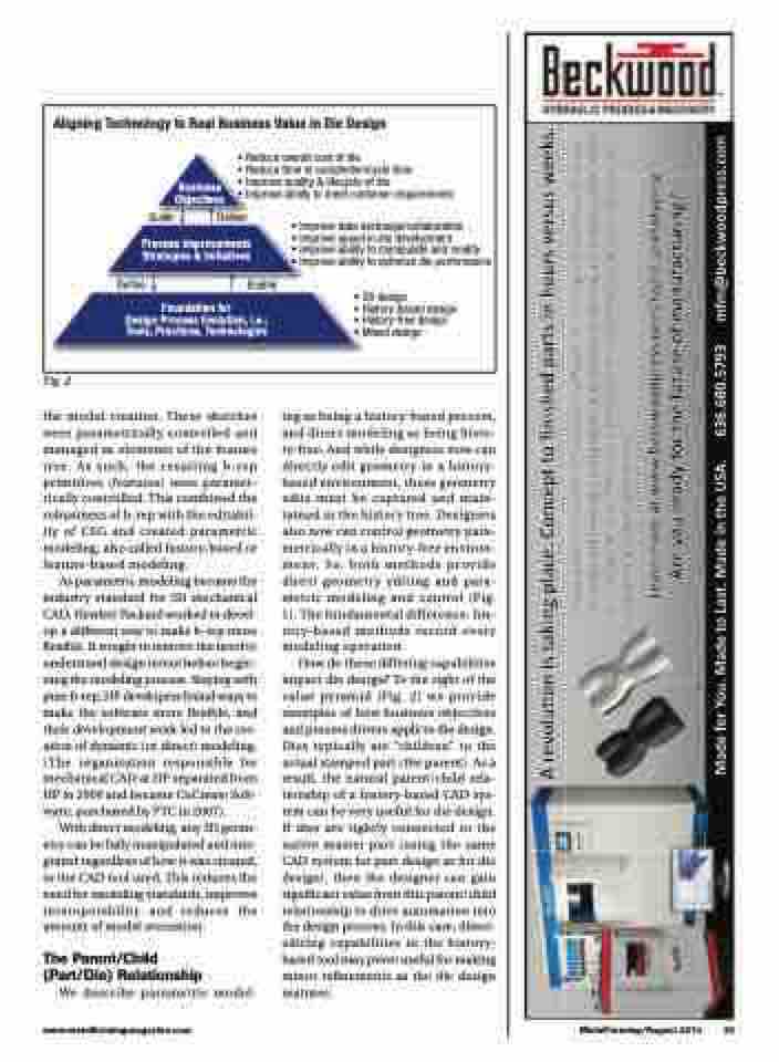
      Aligning Technology to Real Business Value in Die Design
 Guide
Deliver
• Improve data exchange/collaboration
• Improve speed in die development
• Improve ability to manipulate and modify
• Improve ability to optimize die performance
• 2D design
• History-based design • History-free design
• Mixed design
• Reduce overall cost of die
• Reduce time to completion/cycle time Business • Improve quality & lifecycle of die
Objectives • Improve ability to meet customer requirements
   Process Improvements Strategies & Initiatives
  Define
Enable
 Foundation for
Design Process Evolution, i.e.; Tools, Practices, Technologies
              Fig. 2
the model creation. These sketches were parametrically controlled and managed as elements of the feature tree. As such, the resulting b-rep primitives (features) were paramet- rically controlled. This combined the robustness of b-rep with the editabil- ity of CSG and created parametric modeling, also called history-based or feature-based modeling.
As parametric modeling became the industry standard for 3D mechanical CAD, Hewlett Packard worked to devel- op a different way to make b-rep more flexible. It sought to remove the need to understand design intent before begin- ning the modeling process. Staying with pure b-rep, HP developers found ways to make the software more flexible, and their development work led to the cre- ation of dynamic (or direct) modeling. ( The organization responsible for mechanical CAD at HP separated from HP in 2000 and became CoCreate Soft- ware, purchased by PTC in 2007).
With direct modeling, any 3D geom- etry can be fully manipulated and inte- grated regardless of how it was created, or the CAD tool used. This reduces the need for modeling standards, improves interoperability and reduces the amount of model recreation.
The Parent/Child (Part/Die) Relationship
We describe parametric model-
ing as being a history-based process, and direct modeling as being histo- ry-free. And while designers now can directly edit geometry in a history- based environment, these geometry edits must be captured and main- tained in the history tree. Designers also now can control geometry para- metrically in a history-free environ- ment. So, both methods provide direct geometry editing and para- metric modeling and control (Fig. 1). The fundamental difference: his- tory-based methods record every modeling operation.
How do these differing capabilities impact die design? To the right of the value pyramid (Fig. 2) we provide examples of how business objectives and process drivers apply to die design. Dies typically are “children” to the actual stamped part (the parent). As a result, the natural parent/child rela- tionship of a history-based CAD sys- tem can be very useful for die design. If dies are tightly connected to the native master part (using the same CAD system for part design as for die design), then the designer can gain significant value from this parent/child relationship to drive automation into the design process. In this case, direct- editing capabilities in the history- based tool may prove useful for making minor refinements as the die design matures.
      www.metalformingmagazine.com
MetalForming/August 2014 33
����������������������������������������������������������������
��������������������������������������������������������������������� ���������������������������������������������������������������������� ����������������������������������������������������������������������� ����������������������������
��������������������������������������������������
��������������������������������������� �����������������������������������������������������������������������������������������������������������������������������������
����������������������������������� ������������ ���������������������
