
Page 27 - MetalForming August 2014
P. 27
dence that the simulated result will closely mirror the actual forming result, has become an indispensable tool for many.
Users input into the software stan- dard CAD data, properties of the mate- rial being formed and the forming strat- egy, including drawing, stamping, bending, sheet hydroform-
ing and others. In addi-
tion to lowering costs by
eliminating immature
form blocks and flat pat-
terns from the scrap bin, form- ing-simulation software also can
aid the part-quoting process.
“Simulation programs essentially allow our customers to fail faster,” says Scott Pryer, hydroform application engineer for Triform Sheet Hydro- forming. “It’s critical to determine quickly what doesn’t work, so you can move on to what does. Whether you’re quoting a new project and want to uncover hidden obstacles that might impact profitability, or are working with a delivery timeline that won’t tol- erate re-do’s, forming simulations can save the day.”
Powerful forming simu- lation suites also offer inside looks at valu-
able forming- process data.
These insights
can include
material thicken-
ing and thinning dia-
grams, strain charting, force/pressure curves and meas-
Here’s another example of marrying forming simulation and 3D printing of hydroform tooling. Shown are Pam- Stamp models (thickness and major strain) of a formed aluminum (6062-O, 0.040 in. thick) heat- shield, and the resulting 3D-printed form block created on a Stratasys Fortus 400mc printer.
urements showing the distance from the material to the tool’s
surface at any chosen location.
Step 2—Additive-Manufactured Tooling (3D Printing)
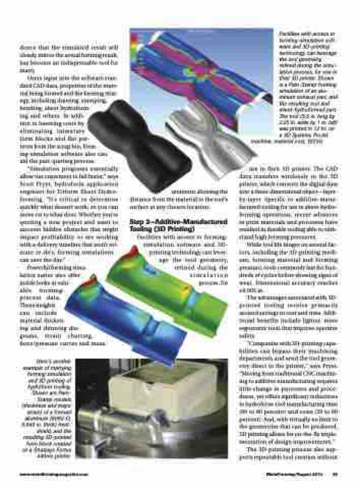
Facilities with access to forming- simulation software and 3D- printing technology can lever-
Facilities with access to forming-simulation soft- ware and 3D-printing technology can leverage the tool geometry, refined during the simu- lation process, for use in their 3D printer. Shown is a Pam-Stamp forming simulation of an alu- minum exhaust part, and the resulting tool and sheet-hydroformed part. The tool (5.5 in. long by 2.25 in. wide by 1 in. tall) was printed in 12 hr. on a 3D Systems ProJet
machine; material cost, $57.50.
use in their 3D printer. The CAD data transfers wirelessly to the 3D printer, which converts the digital data into a three-dimensional object—layer- by-layer. Specific to additive-manu- factured tooling for use in sheet-hydro- forming operations, recent advances in print materials and processes have resulted in durable tooling able to with- stand high forming pressures.
While tool life hinges on several fac- tors, including the 3D-printing medi- um, forming material and forming pressure, tools commonly last for hun- dreds of cycles before showing signs of wear. Dimensional accuracy reaches ±0.005 in.
The advantages associated with 3D- printed tooling revolve primarily around savings in cost and time. Addi- tional benefits include lighter, more ergonomic tools that improve operator safety.
“Companies with 3D-printing capa- bilities can bypass their machining departments and send the tool geom- etry direct to the printer,” says Pryer. “Moving from traditional CNC machin- ing to additive manufacturing requires little change in processes and proce- dures, yet offers significant reductions in hydroform-tool manufacturing time (60 to 80 percent) and costs (50 to 80 percent). And, with virtually no limit to the geometries that can be produced, 3D printing allows for on-the-fly imple- mentation of design improvements.”
The 3D-printing process also sup- ports repeatable tool creation without
age
the tool geometry, refined during the simulation process, for
www.metalformingmagazine.com
MetalForming/August 2014 25
