
Page 32 - MetalForming July 2014
P. 32
Stamping Aluminum
Ra1
Steel
Ra1 =sI/2+sa
sI
sa
Ra2
Aluminum
Ra2 >Ra1
sI
sa
sa: Sheet thickness, outside sI: Sheet thickness, inside
tensile sample begins to rapidly neck and fail as soon as the ultimate tensile strength is reached and the width neck activated.
For similar strengths, steel will fail with total elongations of 40 to 45 per- cent, compared to aluminum values of 24 to 30 percent. Consequently, the experience gained with bending steel cannot be fully transferred to aluminum.
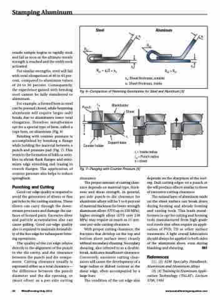
For example, a formed hem in steel can be pressed closed, while hemming aluminum will require larger-radii bends due to aluminum’s lower total elongation. Therefore, metalformers opt for a special type of hem, called a rope hem, on aluminum (Fig. 6)
Bending with counter pressure is accomplished by bending a flange while holding the material between a punch and pressure pad (Fig. 7). This restricts the formation of folds or wrin- kles in shrink flank flanges and mini- mizes edge stretching and tearing in stretch flanges. The application of counter pressure also helps to reduce springback.
Punching and Cutting
Good cut-edge quality is required to avoid the generation of slivers or fine particles in the cutting stations. These slivers can carry through the down- stream processes and damage the sur- faces of formed parts. Excessive sliver and particle accumulation also can cause galling. Good cut-edge quality also is required to maintain formabili- ty of the free edge for subsequent form- ing operations.
The quality of the cut edge relates directly to the alignment of the punch to the die cavity, and the clearance between the punch and die compo- nents. Cutting clearance usually is expressed either as a total clearance— the difference between the punch diameter and the die opening, or (most often) as a per-side cutting
Fig. 6—Comparison of Hemming Geometries for Steel and Aluminum [3]
Punch
s
rst
Blankholder Sheet
rI Support base
Counter holder
rI = Inside radius rst = Punch radius s = sheet
30 MetalForming/July 2014
www.metalformingmagazine.com
Fig. 7—Flanging with Counter Pressure [4]
clearance.
The proper amount of cutting clear-
ance depends on material type, thick- ness and shear strength. In general, per-side punch-to-die clearance for aluminum alloys will be 3 to 8 percent of material thickness for lower-strength aluminum alloys (UTS up to 230 MPa); higher-strength alloys (UTS over 230 MPa) may require as much as 11-per- cent per-side cutting clearance.
With proper cutting clearance, the fractures that develop on the top and bottom sheet surface meet cleanly without secondary shearing. Secondary shearing, also referred to as a double- break, indicates insufficient clearance. Conversely, excessive cutting clear- ances will cause the development of a large radius or dished contour at the shear edge, often accompanied by a large burr.
The condition of the cut edge also
depends on the sharpness of the tool- ing. Dull cutting edges on a punch or die will produce effects similar to those of excessive cutting clearance.
The natural layer of aluminum oxide on the sheet surface can break down during forming and abrade forming and cutting tools. This leads metal- formers to opt for cutting and forming tools manufactured from high-grade tool steels that often require an appli- cation of PVD, TD or other surface treatments. A light overall lubrication should always be applied to both sides of the aluminum sheet, even during blanking and shearing. MF
References
[1], [2] ASM Specialty Handbook: Aluminum and Aluminum Alloys
[3], [4] Training in Aluminum Appli- cation Technology (TALAT), Lecture 3706, 1994
