
Page 30 - MetalForming July 2014
P. 30
Stamping Aluminum
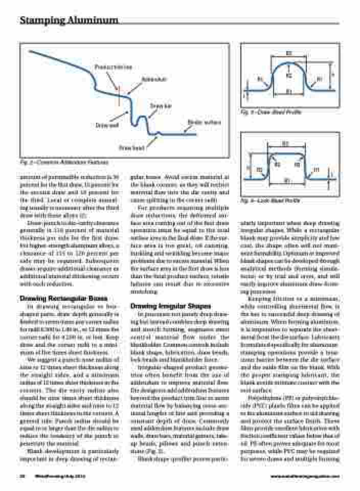
Product trim line
Draw wall
Addendum
Draw bar
Binder surface
Draw bead
Fig. 2—Common Addendum Features
amount of permissible reduction is 30 percent for the first draw, 15 percent for the second draw and 10 percent for the third. Local or complete anneal- ing usually is necessary after the third draw with these alloys [2].
Draw-punch to die-cavity clearance generally is 110 percent of material thickness per side for the first draw. For higher-strength aluminum alloys, a clearance of 115 to 120 percent per side may be required. Subsequent draws require additional clearance as additional material thickening occurs with each reduction.
Drawing Rectangular Boxes
In drawing rectangular or box- shaped parts, draw depth generally is limited to seven times any corner radius for radii 0.500 to 1.00 in., or 12 times the corner radii for 0.250 in. or less. Keep draw and the corner radii to a mini- mum of five times sheet thickness.
We suggest a punch-nose radius of nine to 12 times sheet thickness along the straight sides, and a minimum radius of 12 times sheet thickness in the corners. The die entry radius also should be nine times sheet thickness along the straight sides and nine to 12 times sheet thickness in the corners. A general rule: Punch radius should be equal to or larger than the die radius to reduce the tendency of the punch to penetrate the material.
Blank development is particularly important in deep drawing of rectan-
gular boxes. Avoid excess material at the blank corners, as they will restrict material flow into the die cavity and cause splitting in the corner radii.
For products requiring multiple draw reductions, the deformed sur- face area coming out of the first draw operation must be equal to the total surface area in the final draw. If the sur- face area is too great, oil canning, buckling and wrinkling become major problems due to excess material. When the surface area in the first draw is less than the final product surface, tensile failures can result due to excessive stretching.
Drawing Irregular Shapes
In processes not purely deep draw- ing but instead combine deep drawing and stretch forming, engineers must control material flow under the blankholder. Common controls include blank shape, lubrication, draw beads, lock beads and blankholder force.
Irregular-shaped product geome- tries often benefit from the use of addendum to improve material flow. Die designers add addendum features beyond the product trim line to assist material flow by balancing cross-sec- tional lengths of line and providing a constant depth of draw. Commonly used addendum features include draw walls, draw bars, material gainers, take- up beads, pillows and punch exten- sions (Fig. 2).
Blank shape (profile) proves partic-
Fig. 4—Lock-Bead Profile
ularly important when deep drawing irregular shapes. While a rectangular blank may provide simplicity and low cost, the shape often will not maxi- mize formability. Optimum or improved blank shapes can be developed through analytical methods (forming simula- tions) or by trial and error, and will vastly improve aluminum draw-form- ing processes.
Keeping friction to a minimum, while controlling sheetmetal flow, is the key to successful deep drawing of aluminum. When forming aluminum, it is imperative to separate the sheet- metal from the die surface. Lubricants formulated specifically for aluminum- stamping operations provide a tena- cious barrier between the die surface and the oxide film on the blank. With the proper stamping lubricant, the blank avoids intimate contact with the tool surface.
Polyethylene (PE) or polyvinylchlo- ride (PVC) plastic films can be applied to the aluminum surface to aid drawing and protect the surface finish. These films provide excellent lubrication with friction coefficient values below that of oil. PE often proves adequate for most purposes, while PVC may be required for severe draws and multiple forming
28 MetalForming/July 2014
www.metalformingmagazine.com
R1
R1
h
Fig. 3—Draw-Bead Profile
B2
R2 B1
t
h
R2
B2
B1
R2
R2
R1
t
