
Page 24 - MetalForming July 2014
P. 24
How to Improve Spot-Welding Performance
To avoid skidding, arms and tips of a rocker-arm RSW machine must be per- fectly aligned.
made significant advances. For exam- ple, machines equipped with mid-fre- quency direct-current (MFDC) three- phase inverter power supplies have become common in job shops because they offer many advantages over the traditional single-phase AC machine.
So, ensure good quality by replacing or rebuilding your tired, old RSW machines, or at least retrofit them with new programmable controls.
3) Use the right setup tools.
To make sense of spot-welding recipe charts, every shop using the process should own a specialized resist- ance-welding amp meter to measure the secondary RMS welding current delivered to the tips. In addition, since lever-action variables (on a rocker-arm RSW machine) and ram friction (on a vertical-action press-type machine) can impact the weld force delivered, shops also should have a direct-reading gauge to measure the actual weld force between the tips.
Using a secondary amp meter and force gauge enables an RSW-machine operator to set up the machine scientif- ically rather than through trial-and-error. And, when documentation is required,
some of the available meters also can serve as monitors to record and store welding variables for reference.
4) Use a tensile tester.
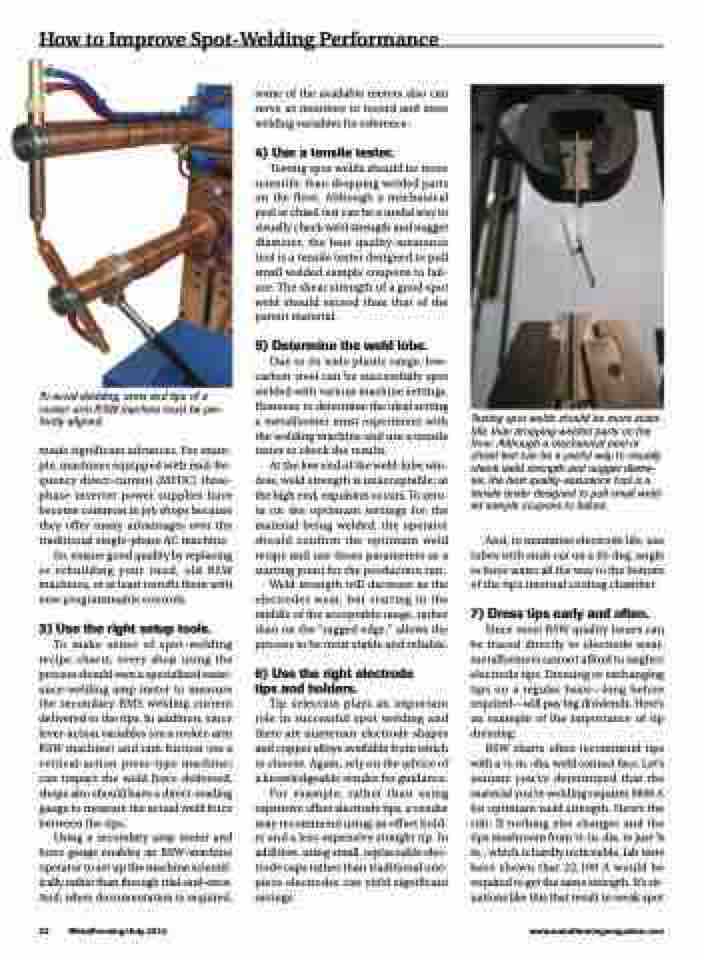
Testing spot welds should be more scientific than dropping welded parts on the floor. Although a mechanical peel or chisel test can be a useful way to visually check weld strength and nugget diameter, the best quality-assurance tool is a tensile tester designed to pull small welded sample coupons to fail- ure. The shear strength of a good spot weld should exceed than that of the parent material.
5) Determine the weld lobe.
Due to its wide plastic range, low- carbon steel can be successfully spot welded with various machine settings. However, to determine the ideal setting a metalformer must experiment with the welding machine and use a tensile tester to check the results.
At the low end of the weld-lobe win- dow, weld strength is unacceptable; at the high end, expulsion occurs. To zero- in on the optimum settings for the material being welded, the operator should confirm the optimum weld recipe and use those parameters as a starting point for the production run.
Weld strength will decrease as the electrodes wear, but starting in the middle of the acceptable range, rather than on the “ragged edge,” allows the process to be most stable and reliable.
6) Use the right electrode tips and holders.
Tip selection plays an important role in successful spot welding and there are numerous electrode shapes and copper alloys available from which to choose. Again, rely on the advice of a knowledgeable vendor for guidance.
For example, rather than using expensive offset electrode tips, a vendor may recommend using an offset hold- er and a less-expensive straight tip. In addition, using small, replaceable elec- trode caps rather than traditional one- piece electrodes can yield significant savings.
Testing spot welds should be more scien- tific than dropping welded parts on the floor. Although a mechanical peel or chisel test can be a useful way to visually check weld strength and nugget diame- ter, the best quality-assurance tool is a tensile tester designed to pull small weld- ed sample coupons to failure.
And, to maximize electrode life, use tubes with ends cut on a 45-deg. angle to force water all the way to the bottom of the tip’s internal cooling chamber.
7) Dress tips early and often.
Since most RSW quality issues can be traced directly to electrode wear, metalformers cannot afford to neglect electrode tips. Dressing or exchanging tips on a regular basis—long before required—will pay big dividends. Here’s an example of the importance of tip dressing:
RSW charts often recommend tips with a 1⁄4-in.-dia. weld contact face. Let’s assume you’ve determined that the material you’re welding requires 9800 A for optimum weld strength. Here’s the rub: If nothing else changes and the tips mushroom from 1⁄4-in. dia. to just 3⁄8 in., which is hardly noticeable, lab tests have shown that 22,100 A would be required to get the same strength. It’s sit- uations like this that result in weak spot
22 MetalForming/July 2014
www.metalformingmagazine.com
