
Page 56 - MetalForming April 2014
P. 56
The Science of Forming By Stuart Keeler
Develop Die-Damage Curves to Avoid Breakage
When flying, do you look out at the airplane engines and won- der if they’ll continue to per- form until you return safely to the ground? Or, do you sit back and relax, confident that the engines are being carefully monitored against a curve showing accumulation of damage as a function of flying hours?
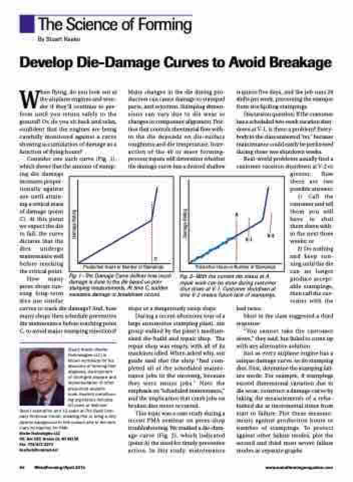
Consider one such curve (Fig. 1), which shows that the amount of stamp- ing die damage
increases propor-
Many changes in the die during pro- duction can cause damage to stamped parts, and rejection. Stamping dimen- sions can vary due to die wear or changes in component alignment. Fric- tion that controls sheetmetal flow with- in the die depends on die-surface roughness and die temperature. Inter- action of the 40 or more forming- process inputs will determine whether the damage curve has a desired shallow
requires five days, and the job runs 20 shifts per week, preventing the stamper from stockpiling stampings.
Discussion question: If the customer has a scheduled two-week vacation shut- down at V-1, is there a problem? Every- body in the class answered “no,” because maintenance could easily be performed during those two shutdown weeks.
Real-world problems usually find a customer vacation shutdown at V-2 or greater. Now there are two possible answers: 1) Call the customer and tell them you will have to shut them down with- in the next three
C
Production Hours or Number of Stampings
A
V-1
Production Hours or Number of Stampings
V-2
tionally against use until attain- ing a critical mass of damage (point C). At this point we expect the die to fail; the curve dictates that the dies undergo maintenance well before reaching the critical point.
Fig. 1—The Damage Curve defines how much damage is done to the die based on prior stamping measurements. At time C, sudden excessive damage or breakdown occurs.
weeks; or
2) Do nothing
and keep run- ning until the die can no longer produce accept- able stampings, then call the cus- tomer with the
How many
press shops run-
ning long-term
dies use similar
curves to track die damage? And, how many shops then schedule preventive die maintenance before reaching point C, to avoid major stamping rejections?
Fig. 2—With the current die status at A, repair work can be done during customer shut down at V-1. Customer shutdown at time V-2 means future lack of stampings.
Stuart Keeler (Keeler Technologies LLC) is known worldwide for his discovery of forming limit diagrams, development of circle-grid analysis and implementation of other press-shop analysis
tools. Keeler’s metalform- ing experience includes 24 years at National
Steel Corporation and 12 years at The Budd Com- pany Technical Center, enabling him to bring a very diverse background to this column and to the sem- inars he teaches for PMA.
Keeler Technologies LLC
P.O. Box 283, Grosse Ile, MI 48138 Fax: 734/671-2271 keeltech@comcast.net
slope or a dangerously steep slope. During a recent afternoon tour of a large automotive stamping plant, our group walked by the plant’s medium- sized die-build and repair shop. The repair shop was empty, with all of its machines idled. When asked why, our guide said that the shop “had com- pleted all of the scheduled mainte- nance jobs in the morning, because they were minor jobs.” Note the emphasis on “scheduled maintenance,” and the implication that crash jobs on
broken dies never occurred.
This topic was a case study during a
recent PMA seminar on press-shop troubleshooting. We studied a die-dam- age curve (Fig. 2), which indicated (point A) the need for timely preventive action. In this study, maintenance
bad news.
Most in the class suggested a third
response:
“You cannot take the customer
down,” they said, but failed to come up with any alternative solution.
Just as every airplane engine has a unique damage curve, so do stamping dies. First, determine the stamping fail- ure mode. For example, if stampings exceed dimensional variation due to die wear, construct a damage curve by taking die measurements of a refur- bished die at incremental times from start to failure. Plot these measure- ments against production hours or number of stampings. To protect against other failure modes, plot the second and third most severe failure modes as separate graphs.
54 MetalForming/April 2014
www.metalformingmagazine.com
Damage Rating
Damage Rating
