
Page 20 - MetalForming December 2013
P. 20
Press Feeding
the material
index occurs in the
proper window of
time allowed by the
press, as well as other operations occur- ring. These include part transfer, die- protection sensing, in-die welding or assembly, and part ejection processes.
A critical feature of the servo-driven roll feed is the human-machine inter- face (HMI)—the device that allows the operator to program and control the servo feed, and that allows the servo feed to communicate important infor- mation back to the operator and press. Servo-feed HMIs and the associated control systems range in sophistica- tion from simple-to-use keypads to process-specific operator interfaces, to fully flexible and programmable touchscreens. Press feed manufactur- ers offer varying levels of memory, communications capability, machine- setup automation and integration with the system, depending on the level of investment. Some fundamental requirements of the HMI and control system:
• Provide job memory storage;
• Allow programmable move pat- terns;
• Provide system troubleshooting and error reporting;
• Record batch counting and pro- duction monitoring data; and
• Allow for easy die threading through various jogging functions.
Move Profiles
With continued advances in servo- control technology, servo-driven roll
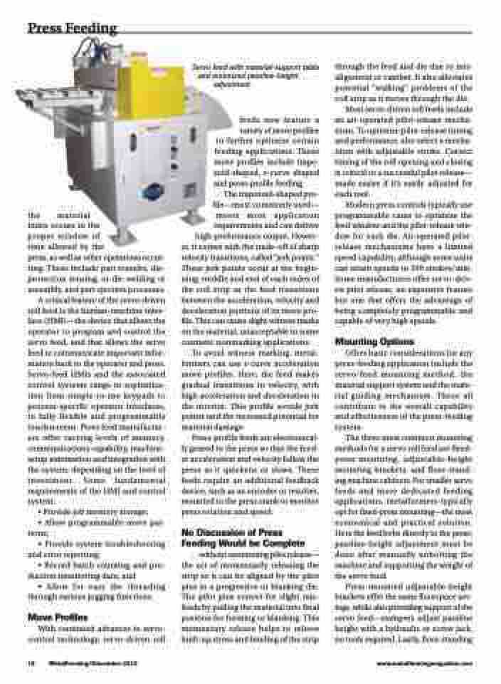
Servo feed with material-support table and motorized passline-height
adjustment.
feeds now feature a
variety of move profiles to further optimize certain feeding applications. These move profiles include trape- zoid-shaped, s-curve shaped
and press-profile feeding. The trapezoid-shaped pro- file—most commonly used— meets most application requirements and can deliver high-performance output. Howev- er, it comes with the trade-off of sharp velocity transitions, called “jerk points.” These jerk points occur at the begin- ning, middle and end of each index of the coil strip as the feed transitions between the acceleration, velocity and deceleration portions of its move pro- file. This can cause slight witness marks on the material, unacceptable in some
cosmetic nonmarking applications. To avoid witness marking, metal- formers can use s-curve acceleration move profiles. Here, the feed makes gradual transitions in velocity, with high acceleration and deceleration in the interim. This profile avoids jerk points and the increased potential for
material damage.
Press-profile feeds are electronical-
ly geared to the press so that the feed- er acceleration and velocity follow the press as it quickens or slows. These feeds require an additional feedback device, such as an encoder or resolver, mounted to the press crank to monitor press rotation and speed.
No Discussion of Press Feeding Would be Complete
...without mentioning pilot release— the act of momentarily releasing the strip so it can be aligned by the pilot pins in a progressive or blanking die. The pilot pins correct for slight mis- feeds by pulling the material into final position for forming or blanking. This momentary release helps to relieve built-up stress and binding of the strip
through the feed and die due to mis- alignment or camber. It also alleviates potential “walking” problems of the coil strip as it moves through the die.
Most servo-driven roll feeds include an air-operated pilot-release mecha- nism. To optimize pilot-release timing and performance, also select a mecha- nism with adjustable stroke. Correct timing of the roll opening and closing is critical to a successful pilot release— made easier if it’s easily adjusted for each tool.
Modern press controls typically use programmable cams to optimize the feed window and the pilot-release win- dow for each die. Air-operated pilot- release mechanisms have a limited speed capability, although some units can attain speeds to 300 strokes/min. Some manufacturers offer servo-driv- en pilot release, an expensive feature but one that offers the advantage of being completely programmable and capable of very high speeds.
Mounting Options
Other basic considerations for any press-feeding application include the servo-feed mounting method, the material support system and the mate- rial guiding mechanism. These all contribute to the overall capability and effectiveness of the press-feeding system.
The three most common mounting methods for a servo roll feed are fixed- press mounting, adjustable-height mounting brackets, and floor-stand- ing machine cabinets. For smaller servo feeds and more dedicated feeding applications, metalformers typically opt for fixed-press mounting—the most economical and practical solution. Here the feed bolts directly to the press; passline-height adjustment must be done after manually unbolting the machine and supporting the weight of the servo feed.
Press-mounted adjustable-height brackets offer the same floorspace sav- ings, while also providing support of the servo feed—stampers adjust passline height with a hydraulic or screw jack, no tools required. Lastly, floor-standing
18 MetalForming/December 2013
www.metalformingmagazine.com
