
Page 48 - MetalForming June 2013
P. 48
Tooling Technology
There is no substitute for seeing soft-
ware in action, via a live demonstration.
Following this test-drive demo, hand the
software salesman a USB drive that
contains the tools, blank outline, materi-
al properties, pad travels and pad forces for a die you recently built. A combination of drawn features, stretch flanges and compression flanges on the stamping you provide covers the gamut of the more difficult forming issues for the software to predict.
perfect. But don’t take my word for it— find out for yourself with live demon- strations.
Beware: Many software companies will perform a canned demo, per- forming the step-by-step simulation live before your eyes. Then, to avoid the wait time for results while the soft- ware runs, they show the finished results from a simulation run ahead of time.
My recommendation: Following this test-drive demo, hand the software salesman a USB drive that contains the tools, blank outline, material prop- erties, pad travels and pad forces for a die you recently built. A combination of drawn features, stretch flanges and compression flanges on the stamping you provide covers the gamut of the more difficult forming issues for the software to predict. Tell them you want to not only watch the setup, but you
because their expertise is in die engi- neering and not FEA.
Die-Face Engineering
Some simulation software offers built-in parametric die face engineer- ing (DFE) functionality. This enables the modeling of the form-tool archi- tecture for each forming operation from the imported product CAD file. The parametric DFE rapidly yields a production-intent die process. Used for production feasibility, this tool- modeling method proves useful at the quote stage of the die-design-and-build transaction. Parametric modeling takes the DFE process from hours down to minutes, while providing the ability to reliably test various product change proposals or alternate die processes without ever having to launch CAD software.
Once the project has been awarded and the stamping has been processed into a progressive-strip layout or trans- fer flowchart, the forming surface design begins in CAD. This CAD-driven DFE then is imported into the incre- mental forming-simulation software for analysis, to validate—or in some cases invalidate—the form-tool sur- faces and mechanics.
There is nothing wrong with having an FEA specialist perform the simula- tions. If the specialist can create die processes with production-die-intent forming-tool surfaces complete with
architectural mechanics, he can per- form the simulation analysis on his own from start to finish.
However, if the FEA expert does not have the knowledge and experience to process the stamping and build
the die-face engineering, a skilled
die engineer will have to perform
this work.
The Value of Live Demonstrations
There is no substitute for seeing software in action, via a live demonstration. Live demos have a way of cutting through smoke and mirrors, so schedule a meeting with at least the software plat- forms on your side of the staffing equation. And to help prevent buyer’s remorse, meet with soft- ware vendors from the other side of the staffing equation as well. The hour or two invested in the sales pitch at least will provide confirmation that your purchase decision was the correct one.
Be prepared for each platform to pitch their brand as the one having the most accurate solver in the business. This kind of state- ment might have had merit five or 10 years ago, but my independ- ent benchmarking effectively takes accuracy out of the equation. And while all of the software brands are reasonably accurate, none are
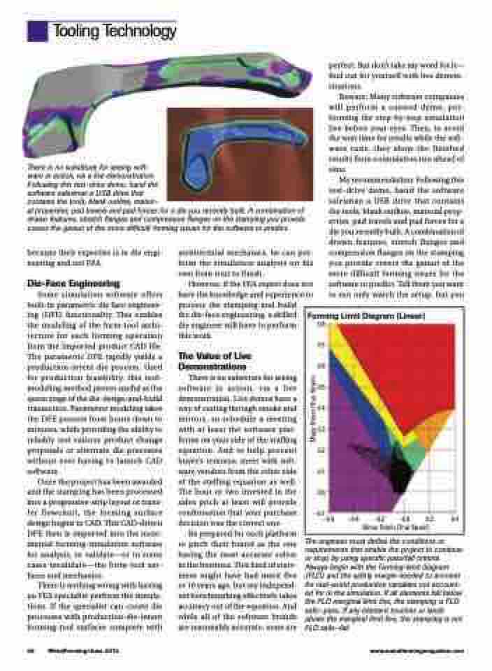
Forming Limit Diagram (Linear)
0.8 0.7 0.6 0.5 0.4 0.3 0.2 0.1 0.0
–0.1
–0.6 –0.4 –0.2
–0.0 0.2 0.4 Minor Strain (True Strain)
46 MetalForming/June 2013
www.metalformingmagazine.com
The engineer must define the conditions or requirements that enable the project to continue or stop, by using specific pass/fail criteria. Always begin with the forming-limit diagram (FLD) and the safety margin needed to account for real-world production variables not account- ed for in the simulation. If all elements fall below the FLD marginal limit line, the stamping is FLD safe—pass. If any element touches or lands above the marginal limit line, the stamping is not FLD safe—fail.
Major Strain (True Strain)
