
Page 51 - MetalForming March 2013
P. 51
Tooling Technology
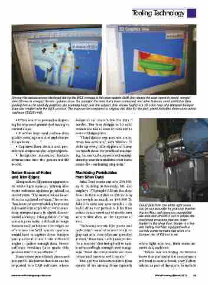
Among the various screen displayed during the WLS process is this scan update (left) that shows the scan operator newly merged data (shown in orange). Screen updates show the operator the data that’s been computed, and what features need additional data, guiding him as he carefully positions the scanning head over the subject. Also shown (right) is a 3D color map of a stamped-bumper draw die, created with the WLS process. The map can be compared to original cad data for the part; green indicates dimensions within tolerance (±0.25 mm).
• Offers adaptive point-cloud spac- ing for improved geometrical tracing in curved areas;
• Provides improved surface-data quality, creating smoother and cleaner 3D surfaces;
• Captures finer details and geo- metrical shapes on the target objects; • Integrates measured feature
dimensions into the generated 3D model.
Better Scans of Holes and Trim Edges
Along with its RE camera upgrade to its white-light scanner, Watson also notes software updates provided in recent years. “The most obvious bene- fit to the updated software,” he notes, “has been the system’s ability to process holes and trim edges when we’re scan- ning stamped parts to check dimen- sional accuracy. Triangulation during scanning can make it difficult to image features such as holes or trim edges, so oftentimes the WLS system operator would have to capture these features using several shots from different angles to gather enough data. Newer software versions have made this process much more efficient.”
Scans create point clouds processed into an STL file format that then can be imported into CAD software, where
designers can manipulate the data if needed. The firm designs in 3D solid models and has 12 seats of Catia and 16 seats of Unigraphics.
“Cloud data is very accurate, some- times too accurate,” says Watson. “It picks up every little ripple and lump, too much detail for practical machin- ing. So, our cad operators will manip- ulate the scan data and smooth it out to create die-machining programs.”
Machining Perishables from Scan Data
Atlas Tool works out of a 250,000- sq.-ft. building in Roseville, MI, and employs 170 people (130 on the shop floor) to turn out dies to 236 in. long that weigh as much as 140,000 lb. Asked to note any new trends in die build, Atlas vice president John Haas points to increased use of steel in new automotive dies, at the expense of iron.
“Subcomponents like posts and pads, which we used to machine from gray cast iron, now often are specified as steel,” Haas says, noting an uptick in the amount of dies being built to tack- le advanced high-strength steel stamp- ings. “Steel die components are more robust and easier to weld-repair.”
Many of the subcomponents Haas speaks of are among those typically
Cloud data from the white-light scans can be too accurate for practical machin- ing, so Atlas cad operators manipulate the data and smooth it out to create die- machining programs that are down- loaded to the shop floor. Shown is a five- axis milling machine equipped with a carbide cutter to make fast work of a bumper die, of D2 tool steel.
white-light scanned, their measure- ment data archived.
“When our stamping customers know that particular die components will tend to wear or break, they’ll often ask us, as part of the quote, to include
www.metalformingmagazine.com
MetalForming/March 2013 49
