
Page 36 - MetalForming January 2013
P. 36
The Science of Forming
By Stuart Keeler
Do Higher Strength Steels Have Less Formability? Part 1
Tooling Technology
High-strength low-alloy (HSLA) steels were the sales leader during the 1970s and ’80s for higher-strength applications. Yield strengths ranged between 35 to 80 KSI, with deformation capacity
sufficient to successfully form most stampings for a variety of industries. Today, weight-reduc- tion programs, greater load-car- rying designs and increased demands for in-service perform- ance have forced companies to order sheet steel with greater as- received yield strengths. To meet these increased requirements, metallurgists have raised the upper yield strengths of HSLA steels to the 100-110 KSI range.
Unfortunately, press shops still
are haunted by the age-old rule of
thumb that formability decreases
as yield strength increases. While
some formability modes have reduced tensile stretchability as yield strength increases, other modes remain unaffected. To explain these differences, the following forming modes are discussed: tensile stretching, compressive deformation, bending, cup drawing, stiffness and springback.
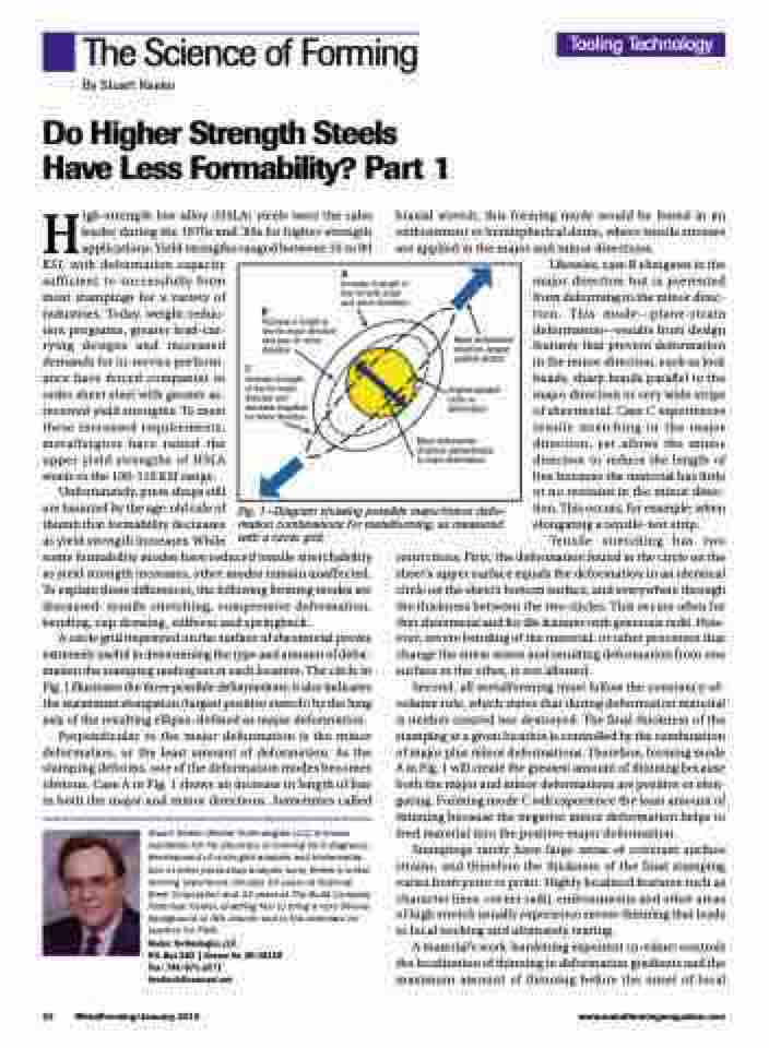
A circle grid imprinted on the surface of sheetmetal proves extremely useful in determining the type and amount of defor- mation the stamping undergoes at each location. The circle in Fig. 1 illustrates the three possible deformations; it also indicates the maximum elongation (largest positive stretch) by the long axis of the resulting ellipse–defined as major deformation.
Perpendicular to the major deformation is the minor deformation, or the least amount of deformation. As the stamping deforms, one of the deformation modes becomes obvious. Case A in Fig. 1 shows an increase in length of line in both the major and minor directions. Sometimes called
Stuart Keeler (Keeler Technologies LLC) is known worldwide for his discovery of forming limit diagrams, development of circle-grid analysis and implementa- tion of other press-shop analysis tools. Keeler’s metal- forming experience includes 24 years at National Steel Corporation and 12 years at The Budd Company Technical Center, enabling him to bring a very diverse background to this column and to the seminars he teaches for PMA.
Keeler Technologies LLC
P.O. Box 283 | Grosse Ile, MI 48138 Fax: 734/671-2271 keeltech@comcast.net
biaxial stretch, this forming mode would be found in an embossment or hemispherical dome, where tensile stresses are applied in the major and minor directions.
Likewise, case B elongates in the major direction but is prevented from deforming in the minor direc- tion. This mode—plane-strain deformation—results from design features that prevent deformation in the minor direction, such as lock beads, sharp bends parallel to the major direction or very wide strips of sheetmetal. Case C experiences tensile stretching in the major direction, yet allows the minor direction to reduce the length of line because the material has little or no restraint in the minor direc- tion. This occurs, for example, when elongating a tensile-test strip.
Tensile stretching has two restrictions. First, the deformation found in the circle on the sheet’s upper surface equals the deformation in an identical circle on the sheet’s bottom surface, and everywhere through the thickness between the two circles. This occurs often for thin sheetmetal and for die features with generous radii. How- ever, severe bending of the material, or other processes that change the stress states and resulting deformation from one
surface to the other, is not allowed.
Second, all metalforming must follow the constancy-of-
volume rule, which states that during deformation material is neither created nor destroyed. The final thickness of the stamping at a given location is controlled by the combination of major plus minor deformations. Therefore, forming mode A in Fig. 1 will create the greatest amount of thinning because both the major and minor deformations are positive or elon- gating. Forming mode C will experience the least amount of thinning because the negative minor deformation helps to feed material into the positive major deformation.
Stampings rarely have large areas of constant surface strains, and therefore the thickness of the final stamping varies from point to point. Highly localized features such as character lines, corner radii, embossments and other areas of high stretch usually experience severe thinning that leads to local necking and ultimately tearing.
A material’s work-hardening exponent (n-value) controls the localization of thinning in deformation gradients and the maximum amount of thinning before the onset of local
Increase in length of line for major direction and zero for minor direction
Increase in length of line for major direction and decrease (negative) for minor direction
Major deformation direction–largest positive stretch
Original gridded circle no deformation
Minor deformation direction–perpendicular to major deformation
A
Increase in length of line for both major and minor directions
B
C
Fig. 1—Diagram showing possible major/minor defor- mation combinations for metalforming, as measured with a circle grid.
34 MetalForming/January 2013
www.metalformingmagazine.com
