
Page 28 - MetalForming August 2012
P. 28
Servo-Drive Presses
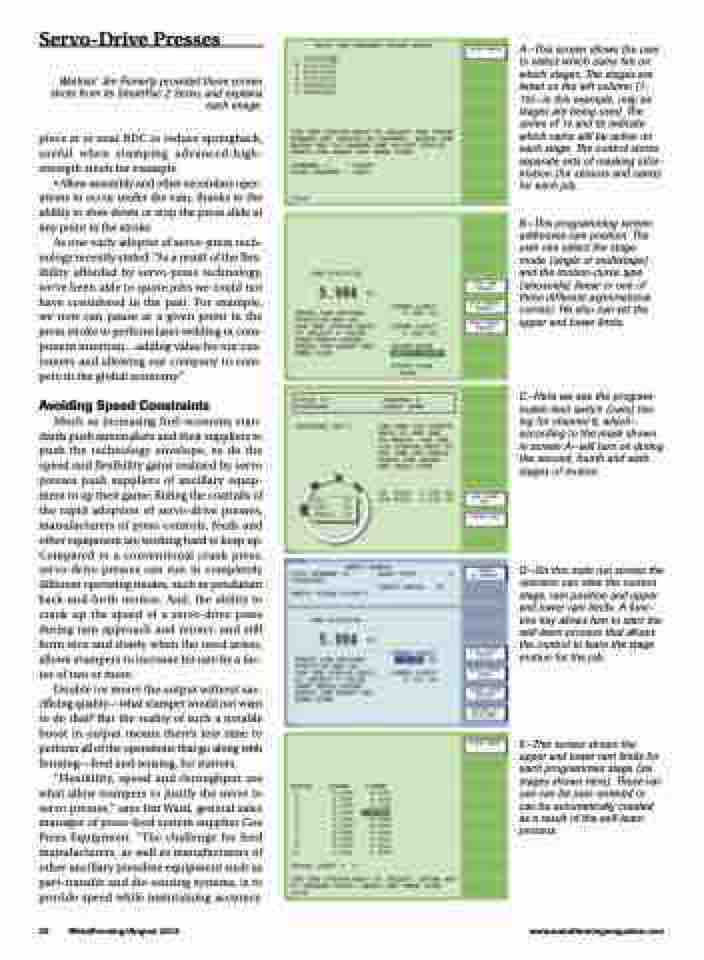
Wintriss’ Jim Finnerty provided these screen shots from its SmartPac 2 Servo, and explains each image.
piece at or near BDC to reduce springback, useful when stamping advanced-high- strength steels for example.
• Allow assembly and other secondary oper- ations to occur under the ram, thanks to the ability to slow down or stop the press slide at any point in the stroke.
As one early adopter of servo-press tech- nology recently stated: “As a result of the flex- ibility afforded by servo-press technology, we’ve been able to quote jobs we could not have considered in the past. For example, we now can pause at a given point in the press stroke to perform laser welding or com- ponent insertion...adding value for our cus- tomers and allowing our company to com- pete in the global economy.”
Avoiding Speed Constraints
Much as increasing fuel-economy stan- dards push automakers and their suppliers to push the technology envelope, so do the speed and flexibility gains realized by servo presses push suppliers of ancillary equip- ment to up their game. Riding the coattails of the rapid adoption of servo-drive presses, manufacturers of press controls, feeds and other equipment are working hard to keep up. Compared to a conventional crank press, servo-drive presses can run in completely different operating modes, such as pendulum back-and-forth motion. And, the ability to crank up the speed of a servo-drive press during ram approach and retract, and still form nice and slowly when the need arises, allows stampers to increase hit rate by a fac- tor of two or more.
Double (or more) the output without sac- rificing quality—what stamper would not want to do that? But the reality of such a notable boost in output means there’s less time to perform all of the operations that go along with forming—feed and sensing, for starters.
“Flexibility, speed and throughput are what allow stampers to justify the move to servo presses,” says Jim Ward, general sales manager of press-feed system supplier Coe Press Equipment. “The challenge for feed manufacturers, as well as manufacturers of other ancillary pressline equipment such as part-transfer and die-sensing systems, is to provide speed while maintaining accuracy.
A—This screen allows the user to select which cams fire on which stages. The stages are listed on the left column (1- 10)—in this example, only six stages are being used. The series of 1s and 0s indicate which cams will be active on each stage. The control stores separate sets of masking infor- mation (for sensors and cams) for each job.
B—This programming screen addresses ram position. The user can select the stage mode (single or multistage) and the motion-curve type (sinusoidal, linear or one of three different asymmetrical curves). He also can set the upper and lower limits.
C—Here we see the program- mable limit switch (cam) tim- ing for channel 8, which— according to the mask shown in screen A—will turn on during the second, fourth and sixth stages of motion.
D—On this main run screen the operator can view the current stage, ram position and upper and lower ram limits. A func- tion key allows him to start the self-learn process that allows the control to learn the stage motion for the job.
E—This screen shows the upper and lower ram limits for each programmed stage (six stages shown here). These val- ues can be user-entered or can be automatically created as a result of the self-learn process.
26 MetalForming/August 2012
www.metalformingmagazine.com
