
Page 66 - MetalForming July 2012
P. 66
Tooling by Design
By Peter Ulintz
Forensic Investigation—
CSI in the Press Shop, Part 3
Tooling Technology
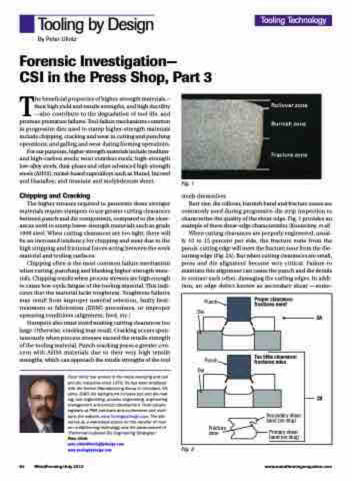
Rollover zone Burnish zone
Fracture zone
The beneficial properties of higher-strength materials— their high yield and tensile strengths, and high ductility —also contribute to the degradation of tool life, and promote premature failures. Tool-failure mechanisms common in progressive dies used to stamp higher-strength materials include chipping, cracking and wear in cutting and punching operations; and galling and wear during forming operations.
For our purposes, higher-strength materials include medium- and high-carbon steels; most stainless steels; high-strength low-alloy steels; dual-phase and other advanced high-strength steels (AHSS); nickel-based superalloys such as Monel, Inconel and Hastalloy; and titanium and molybdenum sheet.
Chipping and Cracking
The higher stresses required to penetrate these stronger materials require stampers to use greater cutting clearances between punch and die components, compared to the clear- ances used to stamp lower-strength materials such as grade 1008 steel. When cutting clearances are too tight, there will be an increased tendency for chipping and wear due to the high stripping and frictional forces acting between the work material and tooling surfaces.
Chipping often is the most common failure mechanism when cutting, punching and blanking higher-strength mate- rials. Chipping results when process stresses are high enough to cause low-cycle fatigue of the tooling material. This indi- cates that the material lacks toughness. Toughness failures may result from improper material selection, faulty heat- treatment or fabrication (EDM) procedures, or improper operating conditions (alignment, feed, etc.)
Stampers also must avoid making cutting clearances too large. Otherwise, cracking may result. Cracking occurs spon- taneously when process stresses exceed the tensile strength of the tooling material. Punch cracking poses a greater con- cern with AHSS materials due to their very high tensile strengths, which can approach the tensile strengths of the tool
Peter Ulintz has worked in the metal stamping and tool and die industries since 1978. He has been employed with the Anchor Manufacturing Group in Cleveland, OH, since 1989. His background includes tool and die mak- ing, tool engineering, process engineering, engineering management and product development. Peter speaks regularly at PMA seminars and conferences and main- tains the website, www.ToolingbyDesign.com. The site serves as a web-based source for the transfer of mod- ern metalforming technology and the advancement of “Performance-Based Die Engineering Strategies.”
Peter Ulintz
pete.ulintz@toolingbydesign.com www.toolingbydesign.com
Fig. 1
steels themselves.
Burr size, die rollover, burnish band and fracture zones are
commonly used during progressive-die strip inspection to characterize the quality of the shear edge. Fig. 1 provides an example of these shear-edge characteristics (Konieczny, et al).
When cutting clearances are properly engineered, usual- ly 10 to 15 percent per side, the fracture zone from the punch-cutting edge will meet the fracture zone from the die- cutting edge (Fig. 2A). But when cutting clearances are small, press and die alignment become very critical. Failure to maintain this alignment can cause the punch and die details to contact each other, damaging the cutting edges. In addi- tion, an edge defect known as secondary shear —some-
Punch Die
Punch Die
Fracture zone
Proper clearance: fractures meet
Too little clearance: fractures miss
Secondary shear band (on slug)
Primary shear band (on slug)
2A
2B
64 MetalForming/July 2012
www.metalformingmagazine.com
Fig. 2
