
Page 37 - MetalForming June 2012
P. 37
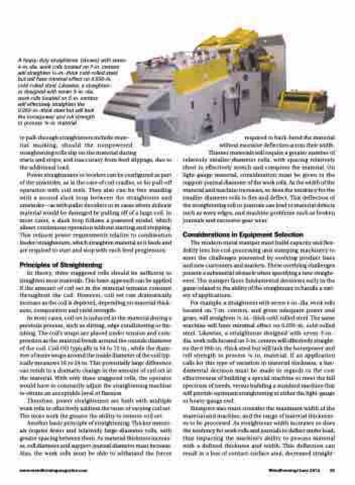
 A heavy-duty straightener (shown) with seven 4-in. dia. work rolls located on 7-in. centers will straighten 1⁄4-in.-thick cold-rolled steel, but will have minimal effect on 0.050-in. cold-rolled steel. Likewise, a straighten-
er designed with seven 3-in.-dia. work rolls located on 5-in. centers will effectively straighten the 0.050-in.-thick steel but will lack the horsepower and roll strength to process 1⁄4-in. material.
to pull-through straighteners include mate-
rial marking, should the nonpowered
straightening rolls slip on the material during
starts and stops; and inaccuracy from feed slippage, due to the additional load.
Power straighteners or levelers can be configured as part of the unwinder, as in the case of coil cradles, or for pull-off operation with coil reels. They also can be free standing with a second slack loop between the straightener and unwinder—as with pallet decoilers or in cases where delicate material would be damaged by pulling off of a large coil. In most cases, a slack loop follows a powered model, which allows continuous operation without starting and stopping. This reduces power requirements relative to combination feeder/straighteners, which straighten material as it feeds and are required to start and stop with each feed progression.
Principles of Straightening
In theory, three staggered rolls should be sufficient to straighten most materials. This basic approach can be applied if the amount of coil set in the material remains constant throughout the coil. However, coil set can dramatically increase as the coil is depleted, depending on material thick- ness, composition and yield strength.
In most cases, coil set is induced in the material during a previous process, such as slitting, edge conditioning or fin- ishing. The coil’s wraps are placed under tension and com- pression as the material bends around the outside diameter of the coil. Coil OD typically is 54 to 72 in., while the diam- eter of inner wraps around the inside diameter of the coil typ- ically measures 16 to 24 in. This potentially large difference can result in a dramatic change in the amount of coil set in the material. With only three staggered rolls, the operator would have to constantly adjust the straightening machine to obtain an acceptable level of flatness.
Therefore, power straighteners are built with multiple work rolls to effectively address the issue of varying coil set. The more work the greater the ability to remove coil set.
Another basic principle of straightening: Thicker materi- als require fewer and relatively large-diameter rolls, with greater spacing between them. As material thickness increas- es, roll diameter and support-journal diameter must increase. Also, the work rolls must be able to withstand the forces
required to back-bend the material without excessive deflection across their width. Thinner materials will require a greater number of relatively smaller-diameter rolls, with spacing relatively short to effectively stretch and compress the material. On light-gauge material, consideration must be given to the support-journal diameter of the work rolls. As the width of the material and machine increases, so does the tendency for the smaller-diameter rolls to flex and deflect. This deflection of the straightening roll or journals can lead to material defects such as wavy edges, and machine problems such as broken
journals and excessive gear wear.
Considerations in Equipment Selection
The modern metal stamper must build capacity and flex- ibility into his coil-processing and stamping machinery to meet the challenges presented by evolving product lines and new customers and markets. These overlying challenges present a substantial obstacle when specifying a new straight- ener. The stamper faces fundamental decisions early in the game related to the ability of the straightener to handle a vari- ety of applications.
For example, a straightener with seven 4-in.-dia. work rolls located on 7-in. centers, and given adequate power and gears, will straighten 1⁄4-in.-thick cold-rolled steel. The same machine will have minimal effect on 0.050-in. cold-rolled steel. Likewise, a straightener designed with seven 3-in.- dia. work rolls located on 5-in. centers will effectively straight- en the 0.050-in.-thick steel but will lack the horsepower and roll strength to process 1⁄4-in. material. If an application calls for this type of variation in material thickness, a fun- damental decision must be made in regards to the cost effectiveness of building a special machine to meet the full spectrum of needs, versus building a standard machine that will provide optimum straightening at either the light-gauge or heavy-gauge end.
Stampers also must consider the maximum width of the material and machine, and the range of material thickness- es to be processed. As straightener width increases so does the tendency for work rolls and journals to deflect under load, thus impacting the machine’s ability to process material with a defined thickness and width. This deflection can result in a loss of contact-surface area, decreased straight-
www.metalformingmagazine.com
MetalForming/June 2012 35
