
Page 49 - MetalForming May 2012
P. 49
assembly issues. The holy grail of measurement systems is to develop one system for the stamping plant that can potentially perform all of the required functions with reliability, repeatability and accuracy, while being highly flexible to enable the user to obtain the measurements he desires shortly after the need for the meas- urement is determined.
Here we present the pros and cons of a few of the most common dimen- sional-measurement systems.
Feeler, Step and
Pin Gauges, and Hole Position/Size Templates
This is the simplest form of stamped- part measurement, providing the die maker and the stamper a good sense of the dimensional accuracy of a panel. While this type of measurement approach typically is simple, the designer/manufacturer of the checking fixture must plan to include rails around the part to enable the use of feeler/step gauges around the panel. This technique enables relatively quick measurements, and allows inspection wherever rails are available—critical for areas of components where paral- lelism matters, such as door outer edges.
A significant disadvantage of this measurement method is the cost incurred to build rails onto fixtures, and the lack of documentation. Over the life of a typical fixture, its use typ- ically will diminish as the stamped product attains dimensional stability. A significant portion of part measure- ment takes place during die verifica- tion and tryout, during which the process stabilizes and the part requires less frequent inspection. Also, we often see use of hand-written documents (sometimes scanned into electronic files) to document these measure- ments, not ideal for entering results into a database for future access. One other significant disadvantage: the lack of repeatability and repro- ducibility, since these techniques are highly operator dependent and require extensive operator training.
Electronic Data Collection Using “Datamytes”
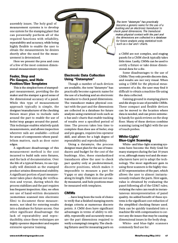
Though a number of such devices are available, the term “datamyte” has practically become a generic name for the use of a bushing and an electronic transducer to check panel dimensions. The transducer makes physical con- tact with the part and the dimensions are collected in a database for future analysis using statistical tools such as x-bar and r charts that enable tracking of results over a specified period of time. The process takes less time to complete than does use of feeler, step and pin gauges, requires less operator skill, and allows for a high degree of repeatability and reproducibility.
Using a datamyte, the process designer must plan for the use of trans- ducers and budget for the cost of the bushings. Also, these standardized transducers allow the user to check part quality only at predetermined, discrete positions, which makes it impossible to measure a part for V-gaps or any changes in the profile along its length. Hole sizes are not eas- ily measured, and hole positions must be measured with templates.
CMMs
...have long been the tools of choice to verify that a finished stamping meets design criteria at numerous discrete points. A CMM does have significant advantages in terms of ability to reli- ably, repeatedly and accurately meas- ure the part dimensions required to verify a stamping’s integrity. The check- ing fixtures used for measuring parts on
The term “datamyte” has practically
become a generic name for the use of a bushing and an electronic transducer to
check panel dimensions. The transducer makes physical contact with the part and
the dimensions are collected in a database for future analysis using statistical tools
such as x-bar and r charts.
a CMM are not complex, and staging panels for a CMM check typically takes little time. Lastly, CMMs can be used to certify a fixture or take dense dimen- sional data for a die.
Some disadvantages to the use of CMMs: They only provide discrete data, and results are not very visual. When using a CMM for the physical meas- urement of a die, the user may find it difficult to obtain a machine file using the data collected.
Gaining ground in stamping plants and die shops is use of portable CMMs. These compact and flexible devices can be moved to the location where data is needed, and can prove extreme- ly handy for quick reviews on the shop floor. Many of these devices combine scanning (using red light) with the use of touch probes.
White-Light/ Blue-Light Scanning
White- and blue-light scanning sys- tems have become the Holy Grail for many stampers during the last 10 years or so, although many tool and die man- ufacturers have yet to adopt the tech- nology. The most significant gain in using these scanners is the highly visu- al 3D representation of the part, which allows the user to almost instanta- neously evaluate the parts. Here again, value is obtained by evaluating the panel following all of the GD&T rules; violating the rules can result in instan- taneous misrepresentation of panel quality. An added benefit of these sys- tems is the significant cost reduction of the simplified checking fixture used. Data can be quickly translated into a machine file with compensation to cor- rect any die issues that may be causing dimensional issues in the body shop.
White- and blue-light scanners commonly find use for:
www.metalformingmagazine.com
MetalForming/May 2012 47
