
Page 42 - MetalForming December 2011
P. 42
Tooling by Design
By Peter Ulintz
Hole Extrusions—Part 3
When the amount of stretching required to form a hole extrusion exceeds the residual stretchability of the punched hole edge, fracturing occurs at the end of the extrusion. Last month we presented several options to restore the edge stretchability of punched holes, including improving the quality of the original cutting operation and making an additional cut of higher quality. The best option: a shaved cut. After a hole has been shaved, we also can coin a small (0.020 in.) radius on the bottom side to compress any burrs that may serve as stress risers.
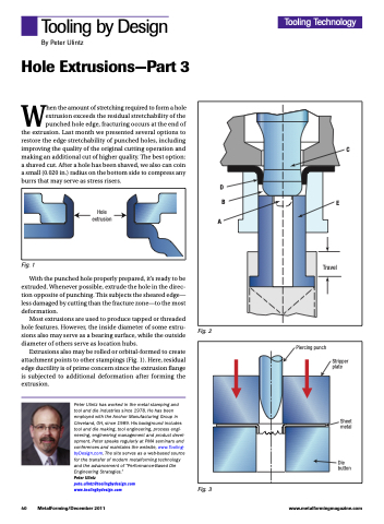
Hole extrusion
Fig. 1
With the punched hole properly prepared, it’s ready to be extruded. Whenever possible, extrude the hole in the direc- tion opposite of punching. This subjects the sheared edge— less damaged by cutting than the fracture zone—to the most deformation.
Most extrusions are used to produce tapped or threaded hole features. However, the inside diameter of some extru- sions also may serve as a bearing surface, while the outside diameter of others serve as location hubs.
Extrusions also may be rolled or orbital-formed to create attachment points to other stampings (Fig. 1). Here, residual edge ductility is of prime concern since the extrusion flange is subjected to additional deformation after forming the extrusion.
Peter Ulintz has worked in the metal stamping and tool and die industries since 1978. He has been employed with the Anchor Manufacturing Group in Cleveland, OH, since 1989. His background includes tool and die making, tool engineering, process engi- neering, engineering management and product devel- opment. Peter speaks regularly at PMA seminars and conferences and maintains the website, www.Tooling- byDesign.com. The site serves as a web-based source for the transfer of modern metalforming technology and the advancement of “Performance-Based Die Engineering Strategies.”
Peter Ulintz
pete.ulintz@toolingbydesign.com www.toolingbydesign.com
Tooling Technology
D B
A
C
E
Travel
Fig. 2
Piercing punch
Stripper plate
Sheet metal
Die button
40 MetalForming/December 2011
www.metalformingmagazine.com
Fig. 3
