
Page 32 - MetalForming July 2011
P. 32
Tooling by Design
By Peter Ulintz
Die Damage at Coil Change
Tooling Technology
If you could create a list of the top-10 stamping-related problems in your press shop, die damage at coil change likely scores high on the list for most shops running pro- gressive dies. There are many causes of die damage at coil change; here are three.
Short feeds (or misfeeds) cause most of the die damage that occurs in press shops. Care must be taken to ensure that the strip starts correctly into the die. Improper positioning of the leading end of the strip will do more damage to the die in the first 10 strokes of the press than the next 10,000 strokes.
To avoid short feeds, minimize the use of round stock lifters that are notched on one side for threading the strip through. While inexpensive and easy to install, they provide less support for the coil strip as compared to a rail-lifter sys- tem. The need to hand-feed the stock through each stock lifter presents an opportunity to make a mistake when starting a new strip. A good rail-lifter system design will reduce setup time and allow higher press speeds because feed problems are minimized. Also, ensure that the lifter systems (or indi- vidual stock lifter, if used) are all at the same height when the die is open. This ensures that the strip is supported in a level plane as it feeds forward.
Be sure that the strip does not sag between any of the lifters. If not corrected, the strip will be pulled out of its correct die position. Again, rail systems generally provide bet- ter support and usually perform better than spring lift pins
or round lifters that are notched on one side.
Extended guide rails with large lead-in angles assist press
operators when starting the strip. Make one of the stock
Peter Ulintz has worked in the sheetmetal-forming industry since 1978. His background includes tool and die making, tool and process engineering, engi- neering management and product development. Peter also operates the website www.ToolingbyDesign.com, a source for the transfer of modern metalforming and tool-and-die technology, and which promotes the use of “Performance-Based Die Engineering Strategies.” Peter Ulintz
pete.ulintz@toolingbydesign.com www.toolingbydesign.com
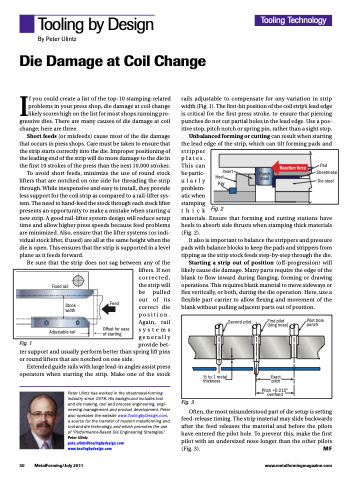
rails adjustable to compensate for any variation in strip width (Fig. 1). The first-hit position of the coil strip’s lead edge is critical for the first press stroke, to ensure that piercing punches do not cut partial holes in the lead edge. Use a pos- itive stop, pitch notch or spring pin, rather than a sight stop.
Unbalanced forming or cutting can result when starting the lead edge of the strip, which can tilt forming pads and stripper
plates.
This can
be partic-
ularly
problem-
atic when
stamping
thickFig.2
materials. Ensure that forming and cutting stations have heels to absorb side thrusts when stamping thick materials (Fig. 2).
It also is important to balance the strippers and pressure pads with balance blocks to keep the pads and strippers from tipping as the strip stock feeds step-by-step through the die.
Starting a strip out of position (off-progression) will likely cause die damage. Many parts require the edge of the blank to flow inward during flanging, forming or drawing operations. This requires blank material to move sideways or flex vertically, or both, during the die operation. Here, use a flexible part carrier to allow flexing and movement of the blank without pulling adjacent parts out of position.
Reaction force
Pad Sheetmetal
Die steel
Insert
Heel Key
Punch steel
Fixed rail
Stock width
Adjustable rail
Feed
Offset for ease of starting
Second pilot
First pilot (long nose)
Exact pitch
Pitch +0.010" overfeed
Pilot hole punch
Fig. 1
1⁄2 to 1 metal thickness
30 MetalForming/July 2011
www.metalformingmagazine.com
Fig. 3
Often, the most misunderstood part of die setup is setting feed-release timing. The strip material may slide backwards after the feed releases the material and before the pilots have entered the pilot hole. To prevent this, make the first pilot with an undersized nose longer than the other pilots (Fig. 3). MF
