
Page 44 - MetalForming June 2011
P. 44
Tooling by Design
By Peter Ulintz
Increasing Press Speed and Efficiency
Your press shop is likely under considerable pressure to reduce the cost of the products (stampings) produced. One way stampers reduce their costs is to increase stamping-press efficiency—produce more parts/hr. But before a plant manager turns up the speed dial on his press- es, he must consider and understand the effect such a move can have on the overall
process.
For example, punch-
ing and cutting at higher
press speeds imparts
higher impact forces on
punch faces and higher
snapthrough forces
(reverse tonnage) on the
punch heads. Impact
occurs when a punch first
makes contact with the
part material. The punch’s
travel stops briefly as
backlash and deflections in the ram and press are absorbed. Compressive loads build rapidly, sending a shock wave up through the punch, and the part material begins to deform. With conventional punch-to-die clearance (5 to 8 per- cent/side), the part material bulges from under the punch face as it compresses into the die matrix.
When the tensile load exceeds the shear strength limit of the part material, the punch cuts through the material until the slug suddenly separates. This sudden unloading of pres- sure on the punch generates a reverse shock that can break punch heads. At the same time, the pierced hole closes up tightly around the punch point. The compressed slug springs back and is held tightly in the die matrix.
Tooling Solutions
To help minimize impact and snapthrough forces, stam- pers can stagger punches in length. Using two or three dif- ferent punch lengths can reduce loads by 30 to 50 percent. A
Peter Ulintz has worked in the sheetmetal-forming industry since 1978. His background includes tool and die making, tool and process engineering, engi- neering management and product development. Peter also operates the website www.ToolingbyDesign.com, a source for the transfer of modern metalforming and tool-and-die technology, and which promotes the use of “Performance-Based Die Engineering Strategies.” Peter Ulintz
pete.ulintz@toolingbydesign.com www.toolingbydesign.com
common practice is to stagger the different groups of punch- es by an amount equal to stock thickness.
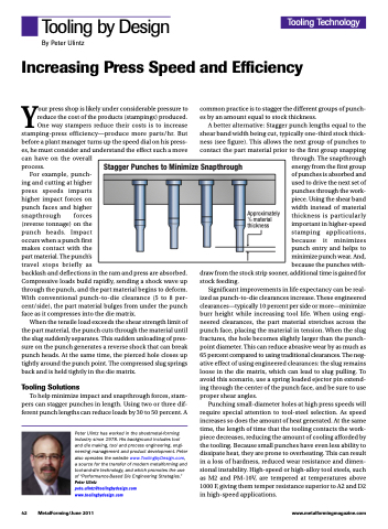
A better alternative: Stagger punch lengths equal to the shear band width being cut, typically one-third stock thick- ness (see figure). This allows the next group of punches to contact the part material prior to the first group snapping
through. The snapthrough energy from the first group of punches is absorbed and used to drive the next set of punches through the work- piece. Using the shear band width instead of material thickness is particularly important in higher-speed stamping applications, because it minimizes punch entry and helps to minimize punch wear. And, because the punches with-
draw from the stock strip sooner, additional time is gained for stock feeding.
Significant improvements in life expectancy can be real- ized as punch-to-die clearances increase. These engineered clearances—typically 10 percent per side or more—minimize burr height while increasing tool life. When using engi- neered clearances, the part material stretches across the punch face, placing the material in tension. When the slug fractures, the hole becomes slightly larger than the punch- point diameter. This can reduce abrasive wear by as much as 65 percent compared to using traditional clearances. The neg- ative effect of using engineered clearances: the slug remains loose in the die matrix, which can lead to slug pulling. To avoid this scenario, use a spring loaded ejector pin extend- ing through the center of the punch face, and be sure to use proper shear angles.
Punching small-diameter holes at high press speeds will require special attention to tool-steel selection. As speed increases so does the amount of heat generated. At the same time, the length of time that the tooling contacts the work- piece decreases, reducing the amount of cooling afforded by the tooling. Because small punches have even less ability to dissipate heat, they are prone to overheating. This can result in a loss of hardness, reduced wear resistance and dimen- sional instability. High-speed or high-alloy tool steels, such as M2 and PM-10V, are tempered at temperatures above 1000 F, giving them temper resistance superior to A2 and D2 in high-speed applications.
Tooling Technology
Stagger Punches to Minimize Snapthrough
Approximately 1/3 material thickness
42 MetalForming/June 2011
www.metalformingmagazine.com
