
Page 29 - MetalForming May 2011
P. 29
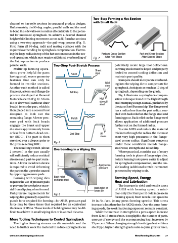
   Two-Step Forming a Hat Section with Small Radii
Part and Cross-Section Part and Cross-Section After First Stage After Second Stage
     Fig. 7
channel or hat-style sections in structural product designs. Unfortunately, the 90-deg. angles, parallel walls and the need to bend the sidewalls over a radius all contribute to the poten- tial for increased springback. To achieve a desired channel height while limiting movement across radii, form hat sections using a two-step approach—the gull-wing process (Fig. 7). First, form all 90-deg. radii and mating surfaces with the required overbending for springback compensation. Flatten- ing the large radius in top of the hat section occurs in the sec- ond operation, which may require additional overbending of the flat, top section to produce
parallel walls.
Multistep forming opera-
tions prove helpful for parts having small, severe geometry features that can only be formed in restrike stations. Another such method is called Shapeset, a form-and-flange die process developed at General Motors Research (Fig. 8). A form die or draw tool (without draw beads) forms the part, which is then placed into a second tool designed to lock out the remaining flange. A lower pres- sure pad with lock beads engages the blank and upper die steels approximately 6 mm or less from bottom-dead cen- ter (BDC). The part is then stretched over a die post prior to the press reaching BDC.
The resulting stretch (about 2 percent) in the part usually will sufficiently reduce residual stresses and part-to-part varia- tions. A lower lockdown device is required to avoid deforming the part on the upstroke caused by opposing pressure pads.
Forming with wiping dies
requires the use of pressure pads
to prevent the workpiece mate-
rial from slipping when formed.
Pad-pressure requirements for
wiping dies generally equal the
punch force required for forming—for AHSS, pressure-pad force may be three times that required for an equivalent thickness of HSLA. These levels of holding force may be dif- ficult to achieve in small wiping dies or in a small die area.
More Tooling Techniques to Control Springback
The higher forming stresses on die materials and the need to further work the material to reduce springback can
potentially create large tool deflections. Forming steels must be keyed and properly heeled to control tooling deflection and maintain part quality.
Stampers should incorporate overbend- ing into the wiping die to compensate for springback. Anticipate as much as 10 deg. of springback, depending on the grade.
Fig. 9 illustrates a springback-compen- sation technique found in the High Strength Steel Stamping Design Manual, published by the Auto/Steel Partnership. The flange steel has a radius less than the part radius, cou- pled with back relief on the flange steel and forming post. Back relief on the flange steel allows application of additional pressure further out on the formed radius.
To coin AHSS and reduce the material thickness through the radius, the die must exert very high pressures in the flange- steel corner radius. Significant concerns under these conditions include flange- steel wear, strength and reliability.
Where practical, consider use of rotary forming tools in place of flange wipe dies. Rotary forming tools prove easier to adjust for springback compensation, and the ten- sile loading (additional stretch increment) generated by wiping tools.
Forming Speed, Energy, Heat and Lubrication
The increase in yield and tensile stress of AHSS with forming speed is mini- mal–only 2 to 3 ksi/per 10-fold increase in forming speed, from tensile-test speed to
10 in./in./sec. (many press forming speeds). This stress increase is less than that for AKDQ steels. Over the same form- ing speeds, the work-hardening exponent remains constant.
While the increase in strength for a press-speed increase from 12 to 16 strokes/min. is negligible, the number of parts, amount of energy and the accompanying heat increases by 33 percent. When changing strength levels (grades) within a steel type, higher-strength grades also require greater force,
  Two-Step Post-Stretch Process
 Punch
1st Step
Punch
Sheet steel
Mild steel
High strength steel
               Fig. 8
2nd Step All steels
  Overbending in a Wiping Die
  Pad
Flange steel
        Back relief
on flange steel
Fig. 9
Lower die
Apply extra pressure
Back relief on lower die
    www.metalformingmagazine.com
MetalForming/May 2011 27
