
Page 34 - MetalForming February 2011
P. 34
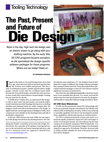
   Tooling Technology
The Past, Present and Future of
Die Design
 Back in the day, high-tech die design was an electric eraser to go along with your drafting machine. By the early ’90s, 2D CAD programs became prevalent, as did specialized die-design-specific software packages for these programs. Where are we today? Read on...
BY RAYMOND PROEBER
Ibegan in this trade as a tool and die apprentice more than 30 yr. ago, when dies were laid out by hand and punches and die sections were milled and ground. This was a time of combination squares, carbide-tipped scribers, height gauges, transfer screws and lots of Dykem layout fluid. Because the tool and die maker controlled the entire process, he also would often work without a formal design, creating his own sketches for the die.
To build more complex dies, an experienced die design- er, who in most cases was previously a tool and die maker, would sometimes provide drawings developed on a drafting machine and drawing board; for really complex dies, the designer would even add some dimensions to his design. As digital readouts started appearing on Bridgeport mills, more components were detailed on the drawing board, typically of perishable components.
In the late 1980s and into the early 1990s, the vast major- ity of die design moved from the drawing board to 2D CAD.
Raymond Proeber is president of Accurate Die Design, Inc., New Berlin, WI, a provider of 3D software, training and sup- port to the tool and die and metal stamping industries, and the U.S. Technical Center for Logopress3: 262/938-9316; www.accuratediedesign.com.
During this same timeframe, U.S. die designers had at their disposal a couple of different die-design software packages that operated within AutoCad. Those that added these spe- cialized software packages to their 2D CAD software enjoyed significant increases in productivity.
Since that time, die making has gradually evolved into much more of an assembly-line process. As a result, tool and die makers have become less prepared to become die designers, and less able to create dies without a design provided to them.
3D CAD Goes Mainstream
In 1995, the first parametric-based 3D CAD package able to run on a personal computer was released. The software only offered solid-modeling functionality, without any surfacing or assembly capability. Over time it was developed to include these capabilities, and became known as a hybrid system.
2D CAD is comprised primarily of lines and circles, so it matured rapidly; parametric-based 3D CAD took longer to evolve. Over the past decade, 3D CAD software has become common in tool and die companies. Why? Productivity—it is practically unheard of for any product design to be developed using 2D as opposed to 3D software. Therefore, there are solid or surface models available for most of the parts for which dies will be designed.
 32 MetalForming/February 2011
www.metalformingmagazine.com
