
Page 30 - MetalForming November 2010
P. 30
Tooling Technology
Stuart Keeler (Keeler Technologies LLC) is best known worldwide for his discovery of forming limit diagrams, development of circle grid analysis and implementation of other press shop analysis tools. Stuart’s sheetmetal forming experience includes 24 years at National Steel Corporation and
12 years at The Budd Company Technical Center, enabling him to bring a very diverse background to this column and the many seminars he teaches for PMA. His most recent project is technical editor of the AHSS Application Guidelines—Version 4.1, which now is available for downloading free from www.worldautosteel.org. Keeler Technologies LLC
P.O. Box 283
Grosse Ile, MI 48138
Fax: 734/671-2271
E-mail: keeltech@comcast.net
High sulfur content can be beneficial for the machinability of many cast- iron parts. In contrast, high sulfur content can greatly reduce the forma- bility, ductility and in-service perform- ance of many steel stampings. The most common problem is manganese sul- fide (MnS) inclusions causing tensile fractures to occur at lower levels of deformation. Press-shop jargon for these inclusions includes internal cracks, stress raisers, notches and other terms highlighting the reduced allowable deformation.
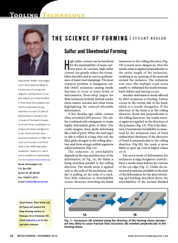
A few decades ago, sulfur content often exceeded 0.050 percent. The sul- fur combined with manganese to create highly deformable globs of MnS. One could imagine these globs deforming like a ball of putty. When the steel ingot or slab is rolled to a long, thin coil, the MnS globs elongate in the rolling direc- tion and form stringy sulfide segments called inclusions (Fig. 1A).
The reduction in stretchability depends on the type and direction of the deformation. In Fig. 1A, the blank is being stretched parallel to the rolling direction. The tensile stress is applied only to the ends of the inclusions, sim- ilar to pulling on the ends of a crack. Very little reduction in stretchability occurs. However, stretching the blank
transverse to the rolling direction (Fig. 1B) is much more dangerous. Now the tensile stress is applied perpendicular to the entire length of the inclusions, resulting in an opening of the material around the inclusion. The inclusions now react like multiple crack zones unable to withstand the tensile stresses. Early failure and tearing occurs.
Another deformation mode affected by MnS inclusions is bending. Failure occurs in the convex side of the bend, which is a tensile elongation. If the direction of the bend is in the rolling direction (bend axis perpendicular to the rolling direction), the tensile stress- es again are applied in the direction of the inclusion (Fig. 1A). This is the direc- tion of maximum bendability as meas- ured by the minimum ratio of bend radius/sheet thickness. If the direction of bend is perpendicular to the rolling direction (Fig.1B), the crack is more likely to open up, even at higher values of r/t.
The worst mode of deformation for inclusions is edge elongation (stretch). Here a tensile stress follows the contour of the cut edge (Fig. 2). Unlike the as- received properties available at the start of the deformation for the sheet stretch- ing and bending described above, the stretchability of the normal blanked
THE SCIENCE OF FORMING Sulfur and Sheetmetal Forming
STUART KEELER
RD
1A
RD
1B
Stuart Keeler, Peter Ulintz and Ed Tarney will present the Deep Drawing seminar on February 16 in Cleveland, OH. Check www.pma.com for this and other seminars.
28 METALFORMING / NOVEMBER 2010
www.metalformingmagazine.com
Fig. 1—Inclusions (A) oriented along the direction of the forming stress (arrows) are less likely to cause fracture than inclusions (B) oriented perpendicular to the forming stress.
