
Page 68 - MetalForming October 2010
P. 68
Tooling Technology
Peter Ulintz has worked in the sheetmetal-forming industry since 1978. His background includes tool and die making, tool and process engineering, engineering management and product devel- opment. Peter also operates the website ToolingbyDesign.com, a source for the transfer of modern metalforming and tool-and-die technology, and which promotes the use of “Performance-Based Die Engineering Strategies.”
Peter speaks at PMA seminars and roundtables focusing on tool and die design, die maintenance, deep drawing, stamping simula- tion, tooling for stamping high- strength steels and problem solv- ing in the press shop.
Peter Ulintz pete.ulintz@toolingbydesign.com www.toolingbydesign.com
My August 2010 column provided incorrect formulas for calculating punch-tip cutting pressures. The proper explanations and formulas should have appeared as follows:
The punching force is the product of the punch tip profile length (L) times the sheetmetal thickness (t) times the sheetmetal’s shear strength (), or:
Fp = (L)(t)()
The shear strength for mild steel is approximately 70 percent of its ulti- mate tensile strength, aluminum is about 50 percent and stainless steel is about 90 percent. Shear strengths also can vary significantly within the same material type. For example, the shear strengths for copper alloys have been reported to be between 50 and 90 per- cent of their ultimate tensile strength, depending on the alloy.
After punching force (Fp) is known, the tip pressure (Pt) can be calculated. For a standard shoulder punch, Pt is equal to the punching force divided by the cross-sectional area (A) of the punch tip:
Pt = Fp / [()(1⁄2d)2]
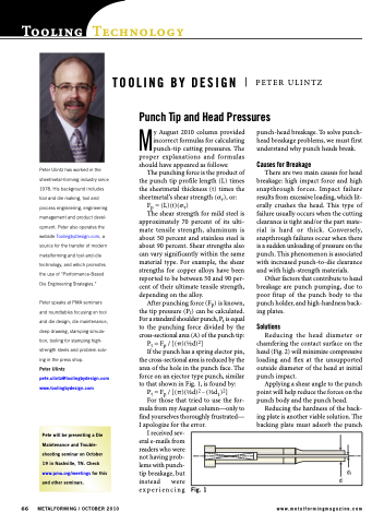
If the punch has a spring elector pin, the cross-sectional area is reduced by the area of the hole in the punch face. The force on an ejector type punch, similar to that shown in Fig. 1, is found by:
Pt = Fp / [()(1⁄2d)2 – (1⁄2d1)2]
For those that tried to use the for- mula from my August column—only to find yourselves thoroughly frustrated— I apologize for the error.
PETER ULINTZ
punch-head breakage. To solve punch- head breakage problems, we must first understand why punch heads break.
Causes for Breakage
There are two main causes for head breakage: high impact force and high snapthrough forces. Impact failure results from excessive loading, which lit- erally crushes the head. This type of failure usually occurs when the cutting clearance is tight and/or the part mate- rial is hard or thick. Conversely, snapthrough failures occur when there is a sudden unloading of pressure on the punch. This phenomenon is associated with increased punch-to-die clearance and with high-strength materials.
Other factors that contribute to head breakage are punch pumping, due to poor fitup of the punch body to the punch holder, and high-hardness back- ing plates.
Solutions
Reducing the head diameter or chamfering the contact surface on the head (Fig. 2) will minimize compressive loading and flex at the unsupported outside diameter of the head at initial punch impact.
Applying a shear angle to the punch point will help reduce the forces on the punch body and the punch head.
Reducing the hardness of the back- ing plate is another viable solution. The backing plate must adsorb the punch
TOOLING BY DESIGN
Punch Tip and Head Pressures
I received sev- eral e-mails from readers who were not having prob- lems with punch- tip breakage, but instead were experiencing
Fig. 1
d1 d
Pete will be presenting a Die Maintenance and Trouble- shooting seminar on October 19 in Nashville, TN. Check www.pma.org/meetings for this and other seminars.
66 METALFORMING / OCTOBER 2010
www.metalformingmagazine.com
