
Page 32 - MetalForming September 2010
P. 32
Tooling Technology
THE SCIENCE OF FORMING
A Different Look at Friction
Remember the so-called “good old days” of metalforming? An accept- able stamping held water or had no smiling tears. Both the low-strength rimmed and aluminum-killed steels had only about 2 or 3 deg. of springback in a bend. For welding two pieces together, this amount of springback was corrected by a strong clamp.
Applications with higher strength steels required stronger clamps. Often a hammer blow replaced the clamps for unexposed applications. Eventually forming transitioned from the two-step process of “form it—then fix it” to the single-step process of “form it correct- ly in the press.”
Springback compensation proce- dures created by extensive trial and error became secret weapons for press shops. Since springback is proportion- al to yield strength, sheetmetal specifi- cations were tightened to reduce the acceptable range of yield strength and other mechanical properties. The thought was reducing the incoming material variability would reduce the final product variability.
STUART KEELER
Stuart Keeler (Keeler Technologies LLC) is best known worldwide for his discovery of forming limit diagrams, development of circle grid analysis and implementation of other press shop analysis tools. Stuart’s sheetmetal forming experience includes 24 years at National Steel Corporation and
12 years at The Budd Company Technical Center, enabling him to bring a very diverse background to this column and the many seminars he teaches for PMA. His most recent project is technical editor of the AHSS Application Guidelines—Version 4.1, which now is available for downloading free from www.worldautosteel.org. Keeler Technologies LLC
P.O. Box 283
Grosse Ile, MI 48138
Fax: 734/671-2271
E-mail: keeltech@comcast.net
Unfortunately, incoming sheetmetal is only one of the input variables to the forming system. What about the lubricant? If consistency of the incoming metal is a highly
desired goal, then consistency
of the lubricant and its applica-
tion should be an equally desir-
able goal. But how are lubricants
treated in too many press shops?
If a stamping is in trouble, the
first reaction is to modify the lubricant. Apply a thicker or
thinner layer of lubricant. Add
more solids or more water. Change the type of lubricant. Combine several types of lubri-
cants for difficult problems—mix some graphite and grease. Most of you are aware of what really happens. Now instead of lubricant changes, press shops realize that the lubricant and its application are a system input that can easily be kept constant and even utilized to minimize the effects of other input inconsistencies.
An extensive study of the effective- ness of lubricants under different form- ing conditions was conducted using a draw bead simulator (DBS). Draw beads are used to control the flow of metal from the binder area over the die radii and into the die opening. Because of the severe bending and unbending through the draw bead, the DBS, designed by Dr. Harmon Nine of the GM Research Cen- ter, was an excellent tool to study the coefficient of friction (COF) of the sheetmetal.
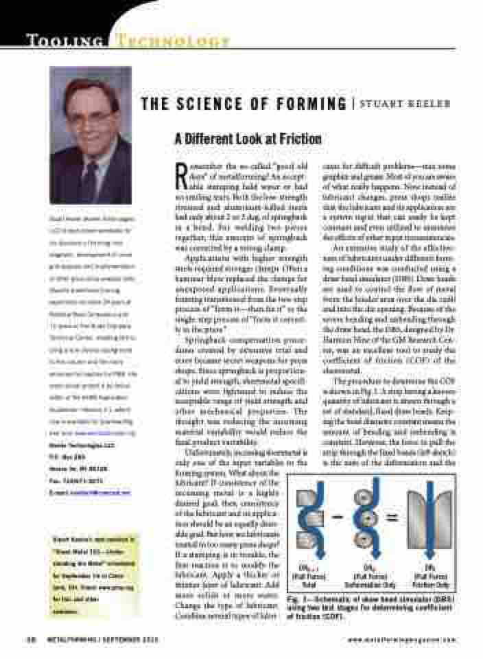
The procedure to determine the COF is shown in Fig. 1. A strip having a known quantity of lubricant is drawn through a set of standard, fixed draw beads. Keep- ing the bead diameter constant means the amount of bending and unbending is constant. However, the force to pull the strip through the fixed beads (left sketch) is the sum of the deformation and the
DRd + f (Pull Force) Total
–=
DRd
(Pull Force) Deformation Only
DRf (Pull Force) Friction Only
Stuart Keeler’s next seminar is “Sheet Metal 101—Under- standing the Metal” scheduled for September 16 in Cleve- land, OH. Check www.pma.org for this and other
seminars.
28 METALFORMING / SEPTEMBER 2010
www.metalformingmagazine.com
Fig. 1—Schematic of draw bead simulator (DBS) using two test stages for determining coefficient of friction (COF).
