
Page 26 - MetalForming July 2010
P. 26
Tooling Technology TOOLING BY DESIGN
PETER ULINTZ
lem associated with shaving operations. Why is slug retention such a prob- lem? Here is my theory: Since the amount of material to be removed by shaving is somewhat related to the size of the fracture zone (die break), many die makers and tool engineers mistak- enly believe that reducing the size of the fracture zone—by reducing the punch-to-die clearance in the punching station—reduces the amount of material being shaved. Thus, reducing shaving- related problems. Actually, this approach
causes more problems than it solves. Reducing punch-to-die cutting clear- ance will produce a larger shear (cut) band, a correspondingly smaller fracture zone and generate small burrs on the backside of the punched holes. A larg- er shear band creates a larger cold- worked zone, which makes shaving more difficult due to the increase in cutting forces, friction, punch fatigue, chipping and punch wear. The burr resulting from the tight clearances inter- feres with accurate part positioning over the matrix opening and it is very difficult to remove by shaving alone. A smaller scrap-ring web also results, making it very difficult to shed the scrap
and keep it out of the die.
The proper punch-to-die clearance,
according to Dayton Progress research, is the largest clearance that does not produce a burr. This can be as much as
Peter Ulintz has worked in the sheetmetal-forming industry since 1978. His background includes tool and die making, tool and process engineering, engineering management and product devel- opment. Peter also operates the website ToolingbyDesign.com, a source for the transfer of modern metalforming and tool-and-die technology, and which promotes the use of “Performance-Based Die Engineering Strategies.”
Peter speaks at PMA seminars and roundtables focusing on tool and die design, die maintenance, deep drawing, stamping simula- tion, tooling for stamping high- strength steels and problem solv- ing in the press shop.
Peter Ulintz pete.ulintz@toolingbydesign.com www.toolingbydesign.com
A Close Shave
Question: I have a low-carbon steel part that is relatively thick—at least it is for us—at 0.125 in. It also has two holes and two tabs with tight tol- erances (±0.001 in.). We would like to produce this part in a progressive die using shave operations rather than hav- ing it fineblanked. Unfortunately, shav- ing in a stamping die is something we have little experience with; could you provide us with some guidelines?
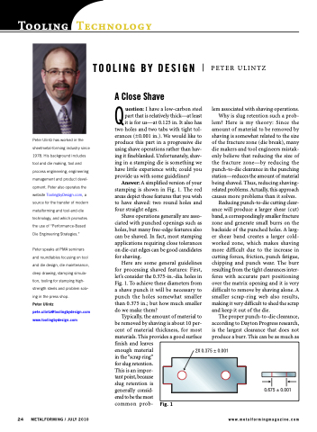
Answer: A simplified version of your stamping is shown in Fig. 1. The red areas depict those features that you wish to have shaved: two round holes and four straight edges.
Shave operations generally are asso- ciated with punched openings such as holes, but many free-edge features also can be shaved. In fact, most stamping applications requiring close tolerances on die-cut edges can be good candidates for shaving.
Here are some general guidelines for processing shaved features: First, let’s consider the 0.375-in.-dia. holes in Fig. 1. To achieve these diameters from a shave punch it will be necessary to punch the holes somewhat smaller than 0.375 in.; but how much smaller do we make them?
Typically, the amount of material to be removed by shaving is about 10 per- cent of material thickness, for most materials. This provides a good surface finish and leaves
enough material
in the “scrap ring”
for slug retention.
This is an impor-
tant point, because
slug retention is
generally consid-
ered to be the most
common prob-
2X 0.375 ± 0.001
24 METALFORMING / JULY 2010
www.metalformingmagazine.com
Fig. 1
0.675 ± 0.001
