
Page 29 - MetalForming March 2010
P. 29
WEDM die block
11⁄2 to 2 times normal clearance
Punch
Normal die clearance
WEDM die block
11⁄2 to 2 times normal clearance
Punch
Normal die clearance
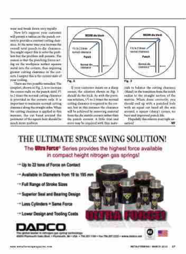
wear and break down very rapidly. Now let’s suppose your customer will permit a radius on the punch cor- ners to provide a constant cutting clear- ance. At the same time you increase the overall total punch-to-die clearance. You might expect this to solve the prob- lem but the problem still persists. The reason is that the punching forces act- ing on the workpiece surface squeeze metal into the corners, thus requiring greater cutting clearance in the cor- ners. I suspect this is the current state of
your tooling.
There are two possible remedies: The
simplest, shown in Fig. 2, is to increase the corner radii on the punch until 11⁄2 to 2 times the normal cutting clearance is provided in the corners only. It is important to maintain normal cutting clearance along the straight sides. When the cutting clearance is applied in this manner, the cut band around the perimeter of the square hole should be much more uniform.
Fig. 2
If your customer insists on a sharp corner, the solution shown in Fig. 3 should do the trick. As with the previ- ous solution, 11⁄2 to 2 times the normal cutting clearance is required in the cor- ner, but in this instance the clearance will be achieved by removing material from the die matrix corners rather than the punch corners. A little trial and error may be required with thin mate-
Fig. 3
rials to balance the cutting clearance (blend) in the transition from the notch radius to the straight section of the matrix. When done correctly, you should end up with a punched hole with an equal cut band all the way around, a square (sharp) corner, no burr and improved punch life.
Hopefully this relieves your tight sit- uation! MF
www.metalformingmagazine.com
METALFORMING / MARCH 2010 27
