
Page 27 - MetalForming November 2009
P. 27
F
Local neck
Uniform elongation
Local neck and fracture
Diffuse neck
A
Yield strength
Diffuse neck Tensile strength
Engineering Strain
Fracture
B
F
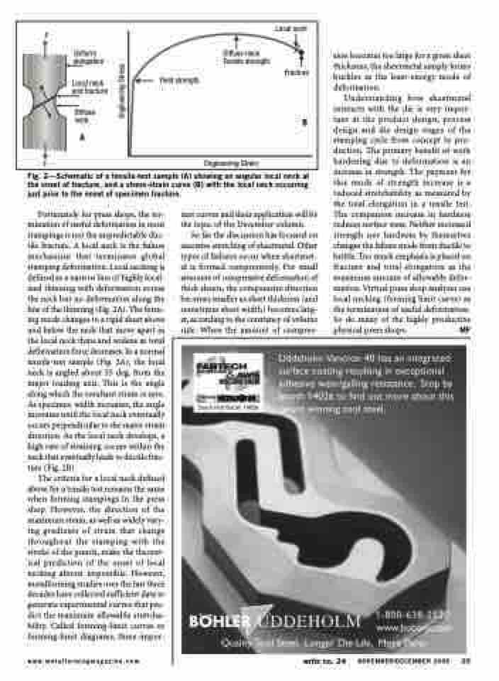
Fig. 2—Schematic of a tensile-test sample (A) showing an angular local neck at the onset of fracture, and a stress-strain curve (B) with the local neck occurring just prior to the onset of specimen fracture.
sion becomes too large for a given sheet thickness, the sheetmetal simply forms buckles as the least-energy mode of deformation.
Understanding how sheetmetal interacts with the die is very impor- tant at the product design, process design and die design stages of the stamping cycle from concept to pro- duction. The primary benefit of work hardening due to deformation is an increase in strength. The payment for this mode of strength increase is a reduced stretchability as measured by the total elongation in a tensile test. The companion increase in hardness reduces surface wear. Neither increased strength nor hardness by themselves changes the failure mode from ductile to brittle. Too much emphasis is placed on fracture and total elongation as the maximum amount of allowable defor- mation. Virtual press shop analyses use local necking (forming limit curve) as the termination of useful deformation. So do many of the highly productive physical press shops. MF
Fortunately for press shops, the ter- mination of useful deformation in most stampings is not the unpredictable duc- tile fracture. A local neck is the failure mechanism that terminates global stamping deformation. Local necking is defined as a narrow line of highly local- ized thinning with deformation across the neck but no deformation along the line of the thinning (Fig. 2A). The form- ing mode changes to a rigid sheet above and below the neck that move apart as the local neck thins and widens as total deformation force decreases. In a normal tensile-test sample (Fig. 2A), the local neck is angled about 55 deg. from the major loading axis. This is the angle along which the resultant strain is zero. As specimen width increases, the angle increases until the local neck eventually occurs perpendicular to the major strain direction. As the local neck develops, a high rate of straining occurs within the neck that eventually leads to ductile frac- ture (Fig. 2B).
The criteria for a local neck defined above for a tensile test remains the same when forming stampings in the press shop. However, the direction of the maximum strain, as well as widely vary- ing gradients of strain that change throughout the stamping with the stroke of the punch, make the theoret- ical prediction of the onset of local necking almost impossible. However, metalforming studies over the last three decades have collected sufficient data to generate experimental curves that pre- dict the maximum allowable stretcha- bility. Called forming-limit curves or forming-limit diagrams, these impor-
tant curves and their application will be the topic of the December column.
So far the discussion has focused on excessive stretching of sheetmetal. Other types of failures occur when sheetmet- al is formed compressively. For small amounts of compressive deformation of thick sheets, the compressive direction becomes smaller as sheet thickness (and sometimes sheet width) becomes larg- er, according to the constancy of volume rule. When the amount of compres-
www.metalformingmagazine.com
write no. 24
NOVEMBER/DECEMBER 2009 25
Engineering Stress
