
Page 33 - MetalForming July/August 2009
P. 33
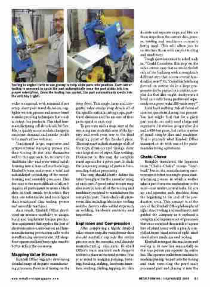
  Tooling is angled (left) to use gravity to help slide parts into position. Each set of tooling is sensored to cycle the part automatically once the part slides into the proper orientation. Once the tooling has cycled, the part automatically ejects into the exit tray (right).
discrete and separate steps, and liberate those steps from the current dies, press- es, tooling and machinery currently being used. This will allow you to restructure them with simpler tooling and machinery.
Tough questions must be asked, such as, “Could I combine this step on the value-stream map that occurs in the left side of the building with a completely different step that occurs several hun- dred feet away?” Or, “Could this hole being pierced on station six in a large pro- gressive die be pierced in a smaller, sim- pler die that also might incorporate a bend currently being performed sepa- rately on a press brake 200 yards away?”
Hold back nothing. Ask all forms of creative questions during this process. You just might find that for a given part you do not really need a large and expensive 14-station progressive die and a 400-ton press, but rather a series of much simpler dies and machines. This is precisely what Kimball Office managed to do with one of its parts- manufacturing operations.
Chaku-Chaku
Roughly translated, the Japanese term “Chaku-Chaku” means “load- load,” but in the manufacturing envi- ronment it refers to a single-piece man- ufacturing process in which a worker takes a part from one workstation to the next—one worker, several tasks. He sets up and operates each machine from the beginning to the end of the pro- duction cycle. This concept is at the core of the Kimball Office philosophy of right-sized tooling and machinery, and guided the company as it replaced a complex and expensive set of processes that once occupied thousands of square feet of plant space with a greatly sim- plified room-sized series of right-sized stand-alone machines and tooling.
Kimball arranged the machines and tooling in its new line sequentially so that one person can operate the entire line. The operator walks from machine to machine placing the part into the tooling and then removing the previously processed part and placing it into the
order is required, with minimal if any setup, short part-travel distances, neg- ligible work in process and sensor-based mistake-proofing techniques that result in defect-free products. This ideal lean- manufacturing cell also should be flex- ible, to quickly accommodate changes in customer demand and enable profits to be made at low volumes.
Traditional large, expensive and setup-intensive stamping presses and their tooling do not lend themselves well to this approach. So, to convert its traditional die- and press-based metal- forming into a lean-cell methodology, Kimball’s team underwent a total and unhindered rethinking of its metal- forming and assembly processes. This first step is the most difficult of all, as it requires all participants to create a blank slate in their minds with which they then can reformulate and reconfigure their traditional dies, tooling, presses and assembly machines.
As a result, Kimball Office devel- oped an inhouse capability to design, build and implement unique produc- tion equipment that applies the best of electronic sensors, automation and lean- manufacturing production cells to the metalforming environment. All shop- floor operations have been right-sized to better-reflect the economy.
Mapping Value Streams
Kimball Office began by developing detailed maps of its parts-manufactur- ing processes, flows and timing on the
shop floor. This single, large and inte- grated value-stream map details all of the specific manufacturing steps, part- travel distances and the amount of time parts spend at each step.
To generate such a map, start at the incoming raw materials area of the fac- tory and work your way to the final shipping point of the finished piece. The map must include drawings of all of the steps, distances and timings, done on a large sheet of paper. Skip nothing. Document on this map the complete travel agenda for a given part. Include the temporary storage of parts in bins, awaiting further processing.
The map should clearly define the total throughput for the manufacturing of each part. A good value-stream map also incorporates all of the tooling and machinery required to manufacture the completed part. This includes all press- room dies, including fabrication tooling and the discrete value-added steps such as welding, hardware assembly and inspection.
Explosion and Compression
After completing a highly detailed value-stream map, the metalformer then should mentally explode the entire process into its essential and discrete manufacturing elements; Kimball Office’s team analyzed each element within its place in the total picture. Free your mind to imagine piercing, form- ing, bending, staking, hardware inser- tion, welding, drilling, tapping, etc. into
www.metalformingmagazine.com
METALFORMING / JULY/AUGUST 2009 31
