
Page 12 - MetalForming July/August 2009
P. 12
TechUpdate
Electric Shakers Minimize Operating Costs, Eliminate Maintenance Requirements
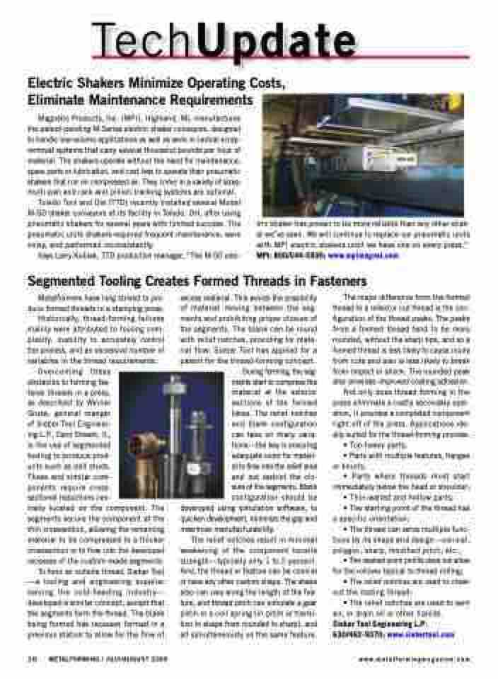
Magnetic Products, Inc. (MPI), Highland, MI, manufactures the patent-pending M-Series electric shaker conveyors, designed to handle low-volume applications as well as work in central scrap- removal systems that carry several thousand pounds per hour of material. The shakers operate without the need for maintenance, spare parts or lubrication, and cost less to operate than pneumatic shakers that run on compressed air. They come in a variety of sizes; multi-pan and rack and pinion tracking systems are optional.
Toledo Tool and Die (TTD) recently installed several Model M-50 shaker conveyors at its facility in Toledo, OH, after using pneumatic shakers for several years with limited success. The pneumatic units shakers required frequent maintenance, were noisy, and performed inconsistently.
Says Larry Kubiak, TTD production manager, “The M-50 elec-
tric shaker has proven to be more reliable than any other shak- er we’ve seen. We will continue to replace our pneumatic units with MPI electric shakers until we have one on every press.” MPI: 800/544-5930; www.mpimagnet.com
Segmented Tooling Creates Formed Threads in Fasteners
Metalformers have long strived to pro- duce formed threads in a stamping press. Historically, thread-forming failures mainly were attributed to tooling com- plexity, inability to accurately control the process, and an excessive number of
variables in the thread requirements. Overcoming these
obstacles to forming fas-
tener threads in a press,
as described by Werner
Gruse, general manger
of Sieber Tool Engineer-
ing L.P., Carol Stream, IL,
is the use of segmented
tooling to produce prod-
ucts such as ball studs.
These and similar com-
ponents require cross-
sectional reductions cen-
trally located on the component. The segments secure the component at the thin crosssection, allowing the remaining material to be compressed to a thicker crosssection or to flow into the developed recesses of the custom-made segments.
To form an outside thread, Sieber Tool —a tooling and engineering supplier serving the cold-heading industry— developed a similar concept, except that the segments form the thread. The blank being formed has recesses formed in a previous station to allow for the flow of
excess material. This avoids the possibility of material moving between the seg- ments and prohibiting proper closure of the segments. The blank can be round with relief notches, providing for mate- rial flow. Sieber Tool has applied for a patent for the thread-forming concept.
During forming, the seg- ments start to compress the material at the exterior sections of the formed lobes. The relief notches and blank configuration can take on many varia- tions—the key is ensuring adequate room for materi- al to flow into the relief area and not restrict the clo- sure of the segments. Blank configuration should be
developed using simulation software, to quicken development, minimize the gap and maximize manufacturability.
The relief notches result in minimal weakening of the component tensile strength—typically only 1 to 2 percent. And, the thread or feature can be conical or have any other custom shape. The shape also can vary along the length of the fea- ture, and thread pitch can simulate a gear pitch or a coil spring (in pitch or transi- tion in shape from rounded to sharp), and all simultaneously on the same feature.
The major difference from the formed thread to a rolled or cut thread is the con- figuration of the thread peaks. The peaks from a formed thread tend to be more rounded, without the sharp tips, and so a formed thread is less likely to cause injury from cuts and also is less likely to break from impact or shock. The rounded peak also provides improved coating adhesion.
Not only does thread forming in the press eliminate a costly secondary oper- ation, it provides a completed component right off of the press. Applications ide- ally suited for the thread-forming process:
• Top-heavy parts;
• Parts with multiple features, flanges or knurls;
• Parts where threads must start immediately below the head or shoulder;
• Thin-walled and hollow parts;
• The starting point of the thread has a specific orientation;
• The thread can serve multiple func- tions by its shape and design—conical, polygon, sharp, modified pitch, etc.;
• The desired point profile does not allow for the rollover typical to thread rolling;
• The relief notches are used to clean out the mating thread;
• The relief notches are used to vent air, or drain oil or other liquids.
Sieber Tool Engineering L.P: 630/462-9370; www.siebertool.com
10 METALFORMING / JULY/AUGUST 2009
www.metalformingmagazine.com
