
Page 45 - MetalForming June 2009
P. 45
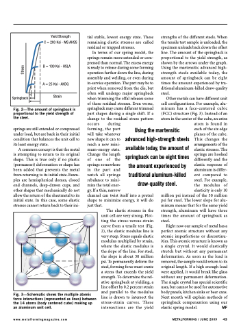
                                                                                                                                                                                                                                                                                                                                            Springback
Yield Strength
C = 200 Ksi - MS AHSS
B = 100 Ksi - HSLA
A = 25 Ksi - AKDQ Strain
tial stable, lowest energy state. These remaining elastic stresses are called residual or trapped stresses.
In terms of our spring model, the springs remain more extended or com- pressed than normal. The excess energy is ready to release during some forming operation further down the line, during assembly and welding, or even during in-service operation. The part may be to print when removed from the die, but often will undergo major springback when trimming the offal releases some of these residual stresses. Even worse, springback may create different trimmed part shapes during a single shift. If a change to the residual stress pattern occurs during
strengths of the different steels. When the tensile test sample is unloaded, the specimen unloads back down the offset line. The amount of the springback is proportional to the yield strength, as shown by the arrows under the graph. Using the martensitic advanced high- strength steels available today, the amount of springback can be eight times the amount experienced by tra- ditional aluminum-killed draw-quality steel.
Other metals can have different unit cell configurations. For example, alu- minum has a face-centered cubic (FCC) structure (Fig. 3). Instead of an atom in the center of the cube, an extra
  Fig. 2—The amount of springback is proportional to the yield strength of the steel.
springs are still extended or compressed under load, but are back in their initial condition that balances the unit cell to its least energy state.
A common concept is that the metal is attempting to return to its original shape. This is true only if no plastic (permanent) deformation or shape has been added that prevents the metal from returning to its initial state. Exam- ples are hemispherical domes, closed end channels, deep-drawn cups, and other shapes that mechanically do not allow the return of the sheetmetal to its initial state. In this case, some elastic stresses cannot return back to their ini-
forming, the part
will take whatever
new shape it can to
reach a new mini-
mum-energy state.
Change the length
of one of the
springs somewhere
in the part and
watch all springs
rebalance to mini-
mize the total ener-
gy. If a thin, narrow
channel can twist itself into a pretzel shape to minimize energy, it will do just that.
atom is found in each of the six edge planes of the cube. This changes the arrangements of the elastic stresses. The springs are hooked differently and the elastic response of aluminum is differ- ent compared to steel. For example, the modulus of elasticity is only 10
million psi instead of the 30 million psi for steel. The lower slope for alu- minum means that for the same yield strength, aluminum will have three times the amount of springback as steel.
Right now our sample of metal has a perfect atomic structure without any atomic imperfections or discontinu- ities. This atomic structure is known as a single crystal. It would elastically stretch but without any permanent deformation. As soon as the load is removed, the sample would return to its original length. If a high enough load were applied, it would break like glass without any permanent deformation. The single crystal has special scientific uses, but cannot be used for automotive body panels, kitchen sinks or beer cans. Next month will explain methods of springback compensation using our elastic spring model. MF
Using the martensitic advanced high-strength steels available today, the amount of springback can be eight times the amount experienced by traditional aluminum-killed draw-quality steel.
                                                                                                                                                                                          Fig. 3—Schematic shows the multiple atomic force interactions (represented as lines) between the 14 atoms (body centered cube) making up an aluminum unit cell.
The elastic stresses in the unit cell are very strong. Plot- ting the stress-versus-strain curve from a tensile test (Fig. 2), the elastic modulus line is very steep. Stress equals elastic modulus multiplied by strain, where the elastic modulus is the slope of the line. For steel, the slope is about 30 million psi. To permanently deform the steel, forming force must create a stress that exceeds the yield strength. To determine the rel- ative springback at yielding, a line offset by 0.2 percent strain and parallel to the modulus line is drawn to intersect the stress-strain curves. These intersections are the yield
www.metalformingmagazine.com
METALFORMING / JUNE 2009 43
Stress
