
Page 44 - MetalForming June 2009
P. 44
Tooling Technology
Stuart Keeler (Keeler Technologies LLC) is best known worldwide for his discovery of forming limit diagrams, development of circle grid analysis and implementation of other press shop analysis tools. Stuart’s sheetmetal forming experience includes 24 years at National Steel Corporation and
12 years at The Budd Company Technical Center, enabling him to bring a very diverse background to this column and the many seminars he teaches for PMA. His most recent project is technical editor of the AHSS Application Guidelines–Version 4, which now is available for downloading free from www.worldautosteel.org. Keeler Technologies LLC
P.O. Box 283
Grosse Ile, MI 48138
Fax: 734/671-2271
E-mail: keeltech@comcast.net
Highly diverse topics have been pre- sented in this column over the past decade. In contrast, for the next half year this column will explore more deeply the fundamentals of how and why sheetmetals deform. The target audience is the personnel in metal- forming companies, and especially the workers on the press floor. These per- sonnel are being exposed to new alloys, advanced high-strength steels, new tech- niques to process sheetmetal into useful parts, special coatings/lubricants, and other sometimes drastic changes that conjure up questions and misunder- standings. Therefore, the explanations will be logical and readily understand- able. Simple illustrations will add addi- tional clarification. Some metallurgists may take exception to the simplicity of the explanations. However, all are designed for press-shop utilization.
The series of columns will include: 1) Elastic stresses (springback)
2) Yielding (start of permanent
deformation)
3) Deformation (work hard-
ening)
4) Failure (necking and frac-
ture)
5) Forming limits (total elon-
gation and forming limit curves) and
6) Surfaces (roughness and coatings).
This month covers the fun- damentals of elastic stresses and springback.
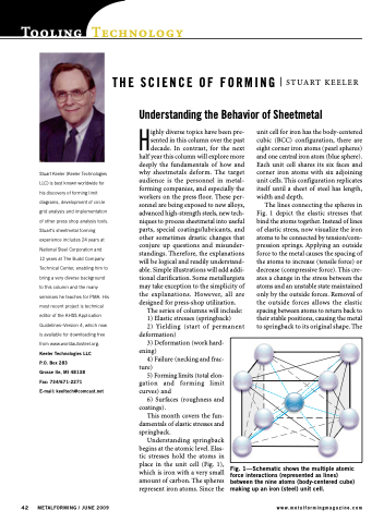
Understanding springback begins at the atomic level. Elas- tic stresses hold the atoms in place in the unit cell (Fig. 1), which is iron with a very small amount of carbon. The spheres represent iron atoms. Since the
unit cell for iron has the body-centered cubic (BCC) configuration, there are eight corner iron atoms (pearl spheres) and one central iron atom (blue sphere). Each unit cell shares its six faces and corner iron atoms with six adjoining unit cells. This configuration replicates itself until a sheet of steel has length, width and depth.
The lines connecting the spheres in Fig. 1 depict the elastic stresses that bind the atoms together. Instead of lines of elastic stress, now visualize the iron atoms to be connected by tension/com- pression springs. Applying an outside force to the metal causes the spacing of the atoms to increase (tensile force) or decrease (compressive force). This cre- ates a change in the stress between the atoms and an unstable state maintained only by the outside forces. Removal of the outside forces allows the elastic spacing between atoms to return back to their stable positions, causing the metal to springback to its original shape. The
THE SCIENCE OF FORMING Understanding the Behavior of Sheetmetal
STUART KEELER
42 METALFORMING / JUNE 2009
www.metalformingmagazine.com
Fig. 1—Schematic shows the multiple atomic force interactions (represented as lines) between the nine atoms (body-centered cube) making up an iron (steel) unit cell.
