
Page 15 - MetalForming June 2009
P. 15
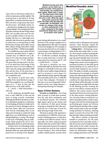
 Modified Knuckle Joint
Slide adjustment
Motion curve, point B
Eccentric drive system Press slide
Flywheel Drive shaft
cases, stress on the frame is kept low to achieve maximum possible rigidity. The nominal load is specified at 30 deg. before BDC to indicate that from here to BDC, the drive components that trans- mit the power—driveshaft, clutch, etc. —also have been designed for the torque corresponding to the nominal press force. Therefore, between 90 and 30 deg. before BDC, the movable parts must be sub- jected to smaller stresses to avoid over- loading. The force-vs.-crank angle curve indicates that the press in question may be subjected to a nominal load of 1000 kN between 30 deg. before BDC and at BDC, while at 90 deg. before BDC a slide load of only FN0/2 = 500 kN is permissible.
If a metalformer uses a press with the parameters specified above to apply a constant force of 1000 kN over a dis- tance h of 5.6 mm, the energy used dur- ingformingisW=Fxh=5600Nm. The press then is being used to the lim- its of its rated force and energy. If the same force were to act over a distance of only 3 mm, the energy expended is 3000 Nm, and the force of the press then is fully used, while the available energy is not completely used.
The situation is much more unfa- vorable if the rated flywheel energy of 5600 Nm is applied over a working dis- tanceofh=3mm.Inthiscase,the effective force of the slide will be:
F = Wn/h = 5600 Nm/0.003m = 1867 kN.
As the maximum permissible press force is only 1000 kN, in this case the press is being severely overloaded. Although the flywheel slowdown is with- in normal limits and gives no indication of overloading, all elements subjected to the press force may be damaged, such as the press frame, slide and connection rods. Serious overloading often occurs when press forming is conducted using high forces over small distances, such as during blanking or coining. The danger is that such overloading may go unde- tected, which requires the use of over- loading safety devices to protect the press.
Another form of overloading results from taking excessive energy from the flywheel, which can cause extremely high press forces to develop if the displace-
Modified knuckle-joint drive systems can be either top- or bottom-mounted. Particularly for solid forming, the modified top- drive system, shown here, is popu- lar. The fixed point of the modi- fied knuckle-joint is mounted in the press crown. While the upper joint pivots around this fixed point, the lower joint describes the curved path, as-illustrated. This results in a change of the stroke- vs.-time characteristic of the slide, compared to the largely symmetrical stroke-time curve of an eccentric drive system.
ment during deformation is too small. However, if the energy is applied over a large displacement, this type of overload is much less dangerous. For example, if the press described above is brought to a stop during a working distance of h = 100 mm, the entire flywheel energy of W = 15,600 Nm is utilized. Assuming that no peak loads have occurred, the mean press force exerted is only F= w/h = 15,600 Nm/0.1 = 156 kN.
The press is, therefore, not over- loaded although the flywheel has been brought to a standstill. In this case, only the drive motor suffers a large slowdown and it is necessary to use a press of a larger flywheel-energy capacity, although the permissible press force of 1000 kN is more than adequate. Overloads of this type occur more frequently if defor- mation is done over a large distance— during deep drawing, for example.
Types of Drive Systems
Eccentric or crank drive—For a long time, eccentric or crank-drive systems, were the only drive mechanism used in mechanical presses. The relatively high impact speed on die closure and the reduction of slide speed during forming are drawbacks that often pre- clude the use of this type of press for deep drawing at high stroke rates.
However, in presses with capacities to a nominal force of 5000 kN, such as uni- versal or blanking presses, a crank drive is still the most effective system. This is especially true when using automated systems where the eccentric drive offers a good compromise between the required processing time and the time required for part transport. Even with the latest crossbar-transfer presses, eccentric-drive
systems used in subsequent processing stations—after drawing—satisfy the requirements for system simplification.
Linkage drive—Attempting to max- imize stroke rates using crank- or eccen- tric-drive systems requires increasing the slide speed. However, when deep draw- ing, ram speed typically must not exceed 0.4 to 0.5 m/sec. during deformation. A linkage-drive system can be designed for mechanical presses so that slide speed during drawing can be reduced by as much as half compared to an eccentric drive. The slide in a double-acting deep- drawing press, for example, is actuated using a specially designed linkage drive. This kinematic characteristic offers ideal conditions for deep drawing. The slide hits the blank softly, allowing it to build up high press forces right from the start of the drawing process, forming the part at a low, almost constant speed. In addition, this system ensures smooth transitions between the various portions of the slide motion. During deforma- tion, the drive links are stretched to an almost extended position; clutch torque, the gear load and the decelerating and accelerating gear masses are between 20 and 30 percent less than with a compa- rable eccentric press. In the case of single- acting machines, for instance, reducing impact increases the service life of the dies, the draw cushion and the press itself.
This offers a number of important benefits in production. For the same nominal press force and slide stroke, a link-drive press can be loaded substan- tially earlier in the stroke, because the press-force displacement curve is steeper within the deformation range. There- fore, a linkage press has a more favorable
www.metalformingmagazine.com
METALFORMING / JUNE 2009 13
