
Page 14 - MetalForming June 2009
P. 14
Fundamentals of
Mechanical- Press Design
Information for this article comes from the MetalForming Handbook, by Schuler GmbH, published in July 1998 by Springer. The hardcover book, 568 pages, is available on Amazon.com.
Force and work are two terms that can be related only by means of a third variable, distance. When force is applied over a certain distance, work is performed. This corresponds in the force-distance graph to the area of the rectangle below the force curve. When work is performed, the distance over which it is performed determines the magnitude of the generated force.
These principles apply to mechanical presses, but rather than a raised weight moving over a distance to perform work, energy is stored in the rotating mass of the press flywheel. Since the energy in the rotating flywheel is only partially used during a press stroke, the electric motor driving the flywheel is not overloaded and does not need to have a large power capacity. In contin- uous operation, a flywheel slowdown of 15 to 20 percent is estimated to be the greatest speed drop permissible. How- ever, this gives no indication of the resulting forces and of the stress exert- ed on the press components.
Press Load
Consider a press with rated force FN0 = 1000 kN = at 30 deg. before bot- tom dead center (BDC); usable energy/ press stroke during continuous opera-
tion WN = 5600 Nm; continuous stroking rate n = 55/min.
Assuming a slowdown of 20 percent during continuous stroking, the usable energy is 36 percent of the total energy available in the flywheel. The overall energy stored in the flywheel:
W = Wn/0.36 = 5600Nm/0.36 = 15,600 Nm.
The given nominal load FN0 in a mechanical press indicates that this value is based on the strength calculations of the frame and the moving elements located in the force flow—crankshaft, connecting rod and slide. Nominal load represents the greatest permissible force in operating the press, defined on the basis of the permissible level of stress or by the deflection characteristics. In most
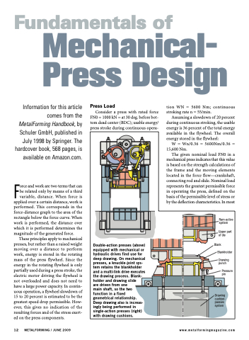
Ram-active system
Upper part of die
Blank Blankholder
Drawing punch
Pressure pin
Double-action presses (above) equipped with mechanical or hydraulic drives find use for deep drawing. On mechanical presses, a knuckle-joint sys- tem retains the blankholder and a multi-link drive executes the drawing process. Blank- holder and drawing slide
are driven from one
main shaft, so the two function in a fixed geometrical relationship. Deep drawing also is increas- ingly being performed in single-action presses (right) with drawing cushions.
Drawing cushion- passive system
12 METALFORMING / JUNE 2009
www.metalformingmagazine.com
