
Page 38 - MetalForming May 2009
P. 38
Tooling Technology
Peter Ulintz has worked in the sheetmetal-forming industry since 1978. His background includes tool and die making, tool and process engineering, engineering management and product devel- opment. Peter also operates the website ToolingbyDesign.com, a source for the transfer of modern metalforming and tool-and-die technology, and which promotes the use of “Performance-Based Die Engineering Strategies.”
Peter speaks at PMA seminars and roundtables focusing on tool and die design, die maintenance, deep drawing, stamping simula- tion, tooling for stamping high- strength steels and problem solv- ing in the press shop.
Peter Ulintz pete.ulintz@toolingbydesign.com www.toolingbydesign.com
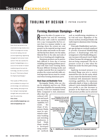
Remove the sides of a square or rec- tangular box and the remaining corner radii could be assembled into a cup. Consequently, the box cor- ners form in a manner similar to cup drawing, where the corners are com- pressive on the material moving toward the die radius and tensile on the mate- rial that has been drawn over the radius. Material flow in the sides and ends of the box is bending and straightening.
Aluminum products can be particu- larly difficult to form due to serious wrinkling and tearing problems associ- ated with their lower forming limits. Because different forming modes and complex material flow are required to produce the corners and side walls, sev- eral important factors must be consid- ered when forming aluminum parts.
Blank Shape and Blankholder Force
such as metalforming simulations or by trial and error. Regardless of the chosen method, developed blanks will vastly improve aluminum draw-forming processes.
Draw pads (blankholders) and nitro- gen-gas springs are routinely employed to provide economical blankholding pressure. A disadvantage with this arrangement is that blankholding pres- sure increases with punch travel (depth of draw) because the nitrogen gas cylin- ders are being compressed. The rise in pressure occurs at a time when the blank area under the draw pad is being reduced.
Applying increased pressure to a decreased flange area acts to restrict material flow into the die cavity, which in turn causes the sheetmetal to stretch. Combined with aluminum’s limited stretching capabilities, the maximum achievable depth of draw is effectively reduced. A more desirable blankholder- force profile is one that decreases in pressure as the blank area is reduced. Such pressure profiles can be achieved
TOOLING BY DESIGN
Forming Aluminum Stampings—Part 2
Rectangular blanks often are cho- sen for simplicity and low cost. While this shape simplifies the manufacturing process, it does not maximize forma- bility. Compared to steel, aluminum- alloy sheet has
reduced stiff-
ness and much
less stretching
capability. As a
result, the
shape of alu-
minum blanks
must be opti-
mized to mini-
mize buckling
and stretching
tendencies. A
final blank
shape usually
is developed
using analyti-
cal methods
PETER ULINTZ
Thickening in the cup wall requires additional punch-to-die clearance to be machined in drawn corners.
Thickening of the flange requires spotting the draw pad to allow free flow of material.
Compression
Stretch bend
Bend and straighten
Box CL
Stretch bend
Bend and straighten
36 METALFORMING / MAY 2009
www.metalformingmagazine.com
Fig. 1—Additional clearance and spotting for improved material flow.
