
Page 21 - MetalForming May 2009
P. 21
• Cradle or a reel?
• Dual reel or a single with a coil car? • Single or dual cradle, or a cradle
with a staging unit behind the primary cradle?
Among the application specifics to consider is the maximum thickness and maximum width the metalformer intends to run. Depending on the max- imum sheet thickness, a cradle may offer a better solution than a vertical reel.
The most common configuration of a compact line, the reel feeder-straight- ener, gets the call when material is not excessively thick and marking of the coil OD is surface critical. A cradle is not a good choice for stampers running very thin material, say 0.016 in. thick, or narrow-width coils. Processing a lot of partial-run coils also sets the stage for using a reel, which makes rewinding the partial coil a simple task provided it’s equipped with proper coil-hold- down arms. Holddown arms also keep the coil tight while rewinding, a difficult if not impossible task to accomplish with a cradle. And, stampers that run dies off center also opt for a reel, since most cradles are self-centering with lit- tle provision for off-center movement.
Having selected a reel setup, now the stamper must choose between a single- or dual-reel installation. A dual- reel system requires room on the plant floor to allow the decoilers to swing out. A single-reel setup with a coil car requires less floor space, and our stud- ies indicate that stampers will experi- ence little difference in coil-change time between a dual-reel setup and a single reel with coil car.
Power Options
To provide sufficient power to decoil and rewind on a reel, the unit typically must include a hydraulic or a variable-
frequency drive. Also, to provide enough power to expand the mandrel on the coil ID, metalformers can opt for a hydraulic-expansion feature. Mechani- cally, expansion is best accomplished with the use of wedges; however, this limits the expansion range. For lighter- weight coils, a linkage mechanism offers greater range but is not as robust.
Another consideration is the degree of automation required. For shops that change jobs frequently and want to eliminate the potential for operator error, an automated system may provide the best solution. Here, an operator enters a job number into the system controller, which has previously been saved, to automatically recall the param- eters for a job.
When specifying an automated line, detail these parameters:
1) Feed length/progression
2) Straightener settings/straightener- roll penetration
3) Speed (strokes/min.)
4) Feed-line height
5) Traversing reel location, based on
the width of the material
6) Coil-cone keeper location, based
on the width of the material
7) Motorized guide rollers—entry
and exit.
Meanwhile, stampers that change
coils less frequently or do not require a great degree of sophistication can make do with a standard line. Specify these parameters:
1) Powered-straightener settings/ straightener-roll penetration
2) Powered feed-line height adjustment
3) Powered peeler and threading table
4) Hydraulic coil-reel expansion and rotation (for power).
With this style of feed line the met- alformer obtains some level of automa- tion, along with manual coil centering and setting of coil-keeper location. Con- sider the addition of a coil car to assist with locating the coil on the mandrel, which will quicken coil changes and pre- vent damage to the coil during loading.
When to Use Cradle-Feed Straightener Lines
Cradle-feed straightener lines offer a good solution when stamping thick and high-strength materials. Safety is of the essence—once the bands are cut, prop- er holddown or containment devices prevent the coil from clock-springing. With the cradle design, the weight of the coil itself helps hold the coil in place, while with a freestanding reel the stam- per must use a holddown device— sometimes multiple devices—to pre- vent the coil from unwinding.
To quicken coil changeovers, stam- pers consider several options. A dual- cradle staging system allows a coil to be placed in a staging cradle directly behind the main powered cradle. As one coil winds out, an arm on the stag- ing cradle pushes the next coil into
www.metalformingmagazine.com
METALFORMING / MAY 2009 19
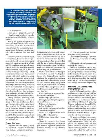
A peeler/threading table promotes hands-free and safe coil threading into the straightener-feeder head. An extend- able peeler tongue reaches the leading edge of the coil to help peel it away from the mandrel, and the threading table pivots to assist in safely moving the coil under the straightening rolls.
