
Page 17 - MetalForming May 2019
P. 17
Tooling by Design
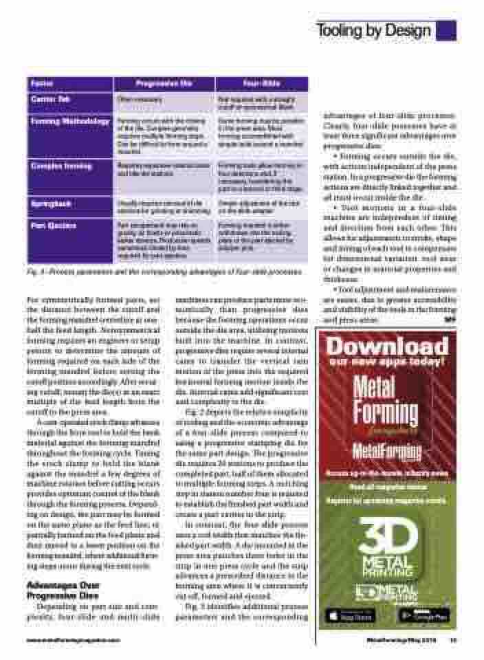
Factor
Progressive Die
Four-Slide
Carrier Tab
Often necessary
Not required with a straight cutoff or symmetrical blank
Forming Methodology
Forming occurs with the closing of the die. Complex geometry requires multiple forming steps. Can be difficult to form around a mandrel.
Some forming may be possible in the press area. Most forming accomplished with simple tools around a mandrel.
Complex forming
Requires expensive internal cams and idle die stations.
Forming tools allow forming in four directions and, if necessary, transferring the part to a second or third stage.
Springback
Usually requires removal of die sections for grinding or shimming
Simple adjustment of the tool on the slide adapter
Part Ejection
Part escapement may rely on gravity, air blasts or pneumatic kicker devices. Production speeds sometimes limited by time required for part ejection.
Forming mandrel is either withdrawn into the tooling plate or the part ejected by stripper pins.
Fig. 3—Process parameters and the corresponding advantages of four-slide processes.
advantages of four-slide processes. Clearly, four-slide processes have at least three significant advantages over progressive dies:
• Forming occurs outside the die, with actions independent of the press station. In a progressive die the forming actions are directly linked together and all must occur inside the die.
• Tool motions in a four-slide machine are independent of timing and direction from each other. This allows for adjustments to stroke, shape and timing of each tool to compensate for dimensional variation, tool wear or changes in material properties and thickness.
• Tool adjustment and maintenance are easier, due to greater accessibility and visibility of the tools in the forming and press areas. MF
Download our new apps today!
Access up-to-the-minute industry news
Read all magazine issues Register for upcoming magazine events
For symmetrically formed parts, set the distance between the cutoff and the forming mandrel centerline at one- half the feed length. Nonsymmetrical forming requires an engineer or setup person to determine the amount of forming required on each side of the forming mandrel before setting the cutoff position accordingly. After secur- ing cutoff, mount the die(s) at an exact multiple of the feed length from the cutoff to the press area.
A cam-operated stock clamp advances through the front tool to hold the bank material against the forming mandrel throughout the forming cycle. Timing the stock clamp to hold the blank against the mandrel a few degrees of machine rotation before cutting occurs provides optimum control of the blank through the forming process. Depend- ing on design, the part may be formed on the same plane as the feed line, or partially formed on the feed plane and then moved to a lower position on the forming mandrel, where additional form- ing steps occur during the next cycle.
Advantages Over Progressive Dies
Depending on part size and com- plexity, four-slide and multi-slide
machines can produce parts more eco- nomically than progressive dies because the forming operations occur outside the die area, utilizing motions built into the machine. In contrast, progressive dies require several internal cams to transfer the vertical ram motion of the press into the required horizontal forming motion inside the die. Internal cams add significant cost and complexity to the die.
Fig. 2 depicts the relative simplicity of tooling and the economic advantage of a four-slide process compared to using a progressive stamping die for the same part design. The progressive die requires 20 stations to produce the completed part, half of them allocated to multiple forming steps. A notching step in station number four is required to establish the finished part width and create a part carrier in the strip.
In contrast, the four-slide process uses a coil width that matches the fin- ished part width. A die mounted in the press area punches three holes in the strip in one press cycle and the strip advances a prescribed distance to the forming area where it is concurrently cut off, formed and ejected.
Fig. 3 identifies additional process parameters and the corresponding
www.metalformingmagazine.com
MetalForming/May 2019 15
