
Page 16 - MetalForming May 2019
P. 16
Tooling by Design
By Peter Ulintz
Four-Slide Tooling
Most of the topics addressed in this column during the past 13 years cover metal stamp- ing processes and dies. However, metal forming includes more than just stamping. Therefore, last month we addressed slide-forming processes. This month’s topic: four-slide tooling. And in coming months we’ll cover more metal forming processes and associ- ated tooling challenges.
Stay tuned.
Essential Elements
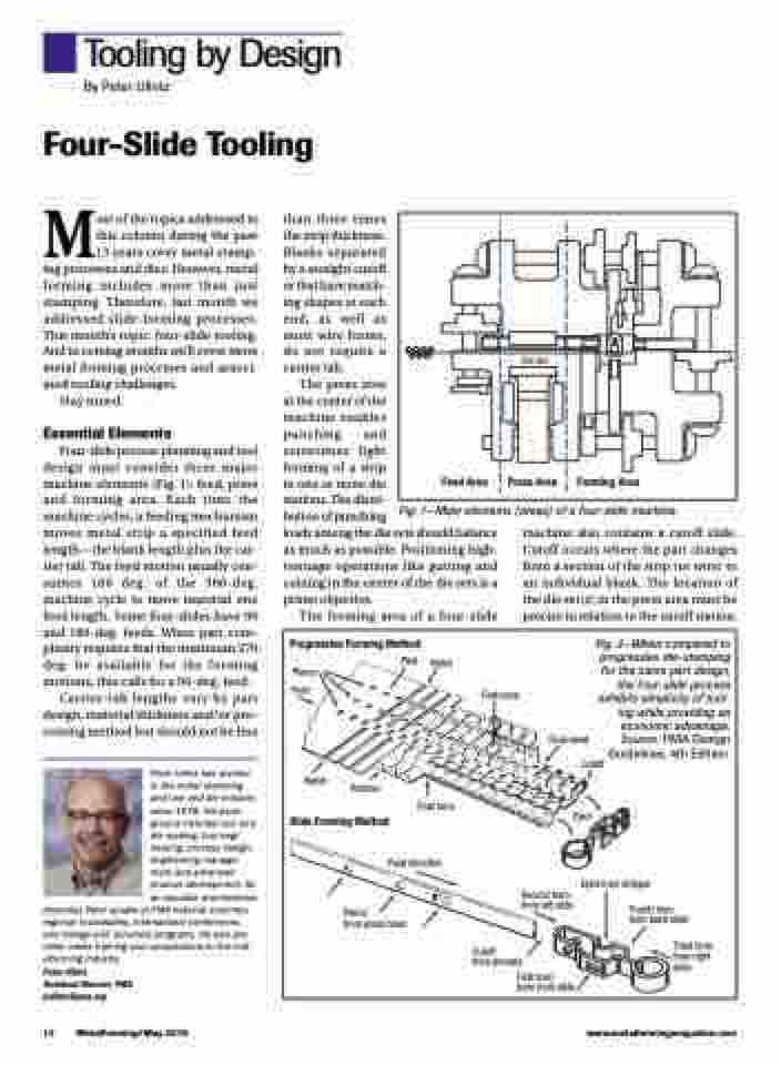
Four-slide process planning and tool design must consider three major machine elements (Fig. 1): feed, press and forming area. Each time the machine cycles, a feeding mechanism moves metal strip a specified feed length—the blank length plus the car- rier tab. The feed motion usually con- sumes 180 deg. of the 360-deg. machine cycle to move material one feed length. Some four-slides have 90 and 180-deg. feeds. When part com- plexity requires that the maximum 270 deg. be available for the forming motions, this calls for a 90-deg. feed.
Carrier-tab lengths vary by part design, material thickness and/or pro- cessing method but should not be less
Peter Ulintz has worked in the metal stamping and tool and die industry since 1978. His back- ground includes tool and die making, tool engi- neering, process design, engineering manage- ment and advanced product development. As an educator and technical
presenter, Peter speaks at PMA national seminars, regional roundtables, international conferences, and college and university programs. He also pro- vides onsite training and consultations to the met- alforming industry.
Peter Ulintz
Technical Director, PMA pulintz@pma.org
than three times the strip thickness. Blanks separated by a straight cutoff or that have match- ing shapes at each end, as well as most wire forms, do not require a carrier tab.
The press area
at the center of the
machine enables
punching and
sometimes light
forming of a strip
in one or more die
stations. The distri-
bution of punching
loads among the die sets should balance as much as possible. Positioning high- tonnage operations like gutting and coining in the center of the die sets is a prime objective.
The forming area of a four-slide
Die Set
Press Area
14 MetalForming/May 2019
www.metalformingmagazine.com
Progressive Forming Method
machine also contains a cutoff slide. Cutoff occurs where the part changes from a section of the strip (or wire) to an individual blank. The location of the die set(s) in the press area must be precise in relation to the cutoff station.
Fig. 2—When compared to progressive die-stamping for the same part design,
the four-slide process
exhibits simplicity of tool-
Pierce Feed
Notch
Preform
Slide Forming Method
First bend
Feed direction
Pierce
from press head
Second form from left slide
Eject from stripper
Fourth form from back slide
Third form from right slide
Pilot
Notch
Final form
Feed Area
Forming Area
Fig. 1—Main elements (areas) of a four-slide machine.
Cutoff
from primary
First form
from front slide
ing while providing an
economic advantage.
Source: PMA Design
Guidelines, 4th Edition.
Eject
Final bend Cutoff
