
Page 39 - MetalForming February 2019
P. 39
Verify that the welding gun’s duty-cycle and amper- age ratings meet application requirements. To avoid excessive wear and premature failure, the gun should not rub against any part of the system.
length. A liner cut too short can cause premature failures of other consum- ables in the system.
4. Reduce Cable Wear
Good cable grounding in the weld cell helps prevent potential problems as the cell ages. Two cables run from the welding power source: one attaches to the wire feeder and the other to the tooling. These cables, often long, may travel from the shop floor to an elevated platform or through wire trays. The section of cable running up the robot or to a positioner will move constantly, causing greater wear over time.
Using a junction with high-flex ground cable at the base of the robot or the workpiece helps reduce down- time and repair costs, requiring only the replacement of a 6-ft. cable section, when worn, rather than replacing per- haps 50 ft. or more of ground cable running all the way back to the power source. However, you should have as few breaks or junctions in the ground- ing cable as possible to maintain a bet- ter electrical connection.
When mounting a ground cable to the welding workpiece, use copper anti-seize lubricant, sometimes referred to as copper slop. This supports the transfer of electrical current and helps prevent the mounting point from fus- ing together or deteriorating over time. The lubricant assists in all areas where grounding current may run run through pins or other semi-permanent contact points.
Proper gun-cable management also extends cable life. The more any cable bends and flexes, the more it will wear and tear, ultimately shortening cable life due to high heat and resistance. Minimize cable bending and flexing in your robotic process and tooling design.
5. Establish TCP
For repeatable and consistent weld
quality, establish and maintain proper tool center point ( TCP). Welding oper- ations can set their own standards for the acceptable amount of TCP drift, depending on the application and type of weld. When considering the toler- ance of TCP variation, half the thick- ness of the wire diameter represents an acceptable starting point.
Many robotic systems today use touch-sensing features to monitor TCP and determine how far it has moved from the original programmed settings. If determined to be out of the acceptable TCP range, the gun neck can be removed and recalibrated offline to factory spec- ifications with a neck straightening fix- ture. Some systems also provide the ability to adjust TCP automatically with the robot. A third option: Leave the gun in place and adjust the robot teaching path to accommodate the modified TCP, though this is the most time-consuming solution. It also requires the need to reprogram the robot if new factory spec- ifications for TCP or a new neck are introduced, making this method the last resort.
Whether every weld cycle, once per shift, or every time the torch goes through a reamer cycle, set a schedule or standard for checking TCP. This prac- tice saves money in lost scrap and rework should a problem occur before welding.
6. Program the Robot Path
The initial programming of the robot’s welding path also involves much trial and error. When program- ming the path, consider the applica- tion, material type, welding process and gap size to be filled. Also impacting weld quality and amount of spatter:
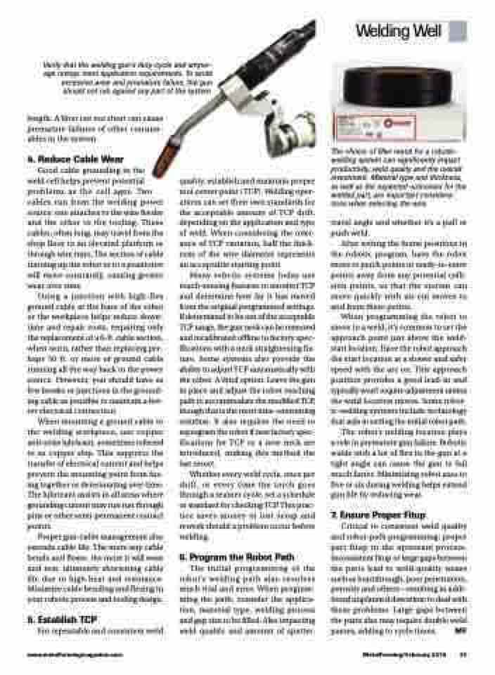
The choice of filler metal for a robotic- welding system can significantly impact productivity, weld quality and the overall investment. Material type and thickness, as well as the expected outcomes for the welded part, are important considera- tions when selecting the wire.
travel angle and whether it’s a pull or push weld.
After setting the home positions in the robotic program, have the robot move to perch points or ready-to-enter points away from any potential colli- sion points, so that the system can move quickly with air-cut moves to and from these points.
When programming the robot to move to a weld, it’s common to set the approach point just above the weld- start location. Have the robot approach the start location at a slower and safer speed with the arc on. This approach position provides a good lead-in and typically won’t require adjustment unless the weld location moves. Some robot- ic-welding systems include technology that aids in setting the initial robot path.
The robot’s welding location plays a role in premature gun failure. Robotic weldswithalotofflexinthegunata tight angle can cause the gun to fail much faster. Minimizing robot axes to five or six during welding helps extend gun life by reducing wear.
7. Ensure Proper Fitup
Critical to consistent weld quality and robot-path programming: proper part fitup in the upstream process. Inconsistent fitup or large gaps between the parts lead to weld-quality issues such as burnthrough, poor penetration, porosity and others—resulting in addi- tional unplanned downtime to deal with these problems. Large gaps between the parts also may require double weld passes, adding to cycle times. MF
www.metalformingmagazine.com
MetalForming/February 2019 37
Welding Well
